Resources
 Part of the Oxford Instruments Group
Expand
Collapse
Part of the Oxford Instruments Group
Technical Article
Author: Dr. Jo Walters
Published: 01 Apr 2023 · Last updated: 11 Sep 2025
Sensitivity is a key performance feature of any detection system. When assessing the sensitivity of any sensor it is the Signal-to-Noise Ratio (SNR) which is of key importance. This demonstrates the ability of the signal to rise above the surrounding noise.
To achieve best possible SNR ratio we need a) capture as much of the signal as possible (highest possible quantum efficiency) and b) to reduce the various sources of noise to a minimum – and achieve the lowest noise floor.
Quantum Efficiency (QE) is the ability of the sensor to convert incoming photons into a measurable electronic signal. QE is usually expressed as a probability or percentage, so a QE of 0.8 or 80% indicates an 80% chance that a photoelectron will be released for each incident photon. QE is wavelength (photon energy) dependent. A sensor is generally chosen which has the highest QE in the wavelength region of interest. All of the 3 examples of Andor cameras shown in this article have excellent QE over the ranges typically required in their intended applications.
| Camera Type | CCD (back-illuminated) | sCMOS | EMCCD |
| Camera Model | iKon-XL 231 BEX2 | ZL41 Cell sCMOS | iXon Ultra 897 |
| QEpeak | >90% | <82% | >95% |
| Typical Applications | Large Sky Surveys, Exoplanet Studies | Fluorescence Microscopy Imaging | Biophysics, Quantum Imaging |
To improve the quantum efficiency of scientific sensors, the following methods have been used:
For these sensors, the important sources of noise are:
1. Sensor readout or read noise NR
2. Thermal or dark noise ND
3. The noise from the signal itself: photon shot noise NSN
4. Clock Induced Charge Noise NCIC which is important for electron multiplication cameras such as EMCCD (But not relevant for CCD or sCMOS).
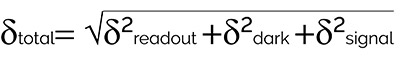
The total camera noise is the sum, in quadrature - the square root of the sum of the various square of the noises:
The readout noise is an inherent property of the sensor and except for special case of EMCCD cameras, is usually the limit of sensitivity for most cameras. The readout noise is a combination of noise sources, which originate from the process of amplifying and converting the photoelectrons to a voltage. Over the years readout noise has improved. But the faster the readout of the camera, the higher the noise, due to the increasing bandwidth required. Low noise CCD’s in the past have typically employed very low readout speeds and so are known as Slow Scan CCD's.
The read noise of an sCMOS camera is very low compared to CCDs and can be less than 1 electron in the latest sCMOS cameras. The read noise of EMCCD is in effect almost eliminated, making them single photon sensitive. The sensor does have a read noise, however there is a process prior to this readout step called Electron Multiplication that boosts the signal many fold in a controlled manner. This has the result that the signal is now so much higher than the noise floor. It is this unique feature of EMCCD that still makes them the choice for the most low-light applications such as single molecule biophysics and the field of quantum imaging.
| Camera Type | CCD (back illuminated) | sCMOS | EMCCD |
| Camera Model | iKon-XL 231 BEX2 | ZL41 Cell sCMOS | iXon Ultra 897 |
| Read Noise | 2.1 e-@100kHz | ~ 1 e- | <1e- |
| Dark Current e-/pixel/sec | 0.6 at -60° C 0.00013 at -100° C | 0.1 At 0°C 0.019 at -10° C | 0.00030 at -80°C |
The second source of noise is dark noise, also commonly called dark current. It arises from heat generated ionisation in the silicon sensor. It is called dark noise as this noise is generated without any signal applied i.e. in total darkness. Recent improvements in sensor design have greatly diminished dark noise to negligible levels and reduced their contribution to total read-out noise. For ultimate sensitivity, cooling the sensor to temperatures as low as -100°C is still required.
Some cameras that run at ambient temperatures and feature passive cooling, may have such a low dark signal that it can be ignored for integration periods of a second or less. However, cooling reduces the dark signal and permits much longer integration periods, up to several hours, without significant dark charge accumulation. Active cooling using thermos-electric cooling and air or liquid cooling is required to achieve low sensor temperatures of -25, -45 or even -100°C. This necessitates the sensor being enclosed in a true vacuum to avoid condensation on the sensor. Unique vacuum seal technology is found on Andor cameras such as the iXon EMCCD, Sona and Marana back-illuminated sCMOS.
The noise arising from the dark charge is given by Poisson statistics as the square root of the charge arising from the thermal effects:

The incoming photons have an inherent noise known as photon shot noise. If for example, we measured the signal from a calibrated and constant light source the value would fluctuate. At first glance this would appear to be noise from the camera, however this effect can be attributed to the variability of the signal itself. A number of photons P in a pixel with QE, DQE would generate noise δsignal the square root of DQEP:

Clock Induced Charge Noise (NCIC) is spurious noise generated during the clocking of the pixels (voltages pulses) when moving the charge out of the sensor. This is minimised by implementation of fine-tuned and well controlled clocking voltages, in particular fine control over clocking edges down to nanosecond resolutions. Since the other sources of noise are so low with EMCCD technology, clock Induced charge remained as the main source of noise in most EMCCD experiments.
Usually, a high-performance camera is operated at certain temperatures and clocking speeds so that the detection limit is determined by the readout noise. The various sources of noise may be added in quadrature to give the overall system or camera noise which may be expressed as:

The system noise characteristics for a typical iDus – BRDD (Deep Depletion) CCD camera are shown in Figure 1.
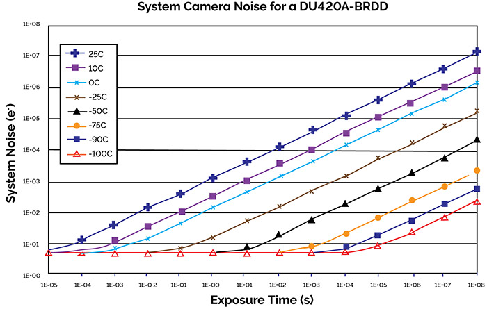
Figure 1: How system noise varies with exposure time and sensor temperature for an iDUS CCD Back illuminated Deep Depletion Camera
With increase in exposure times the dark noise will rise so that for long exposures the overall system noise (and consequently the detection limit) is dominated by the dark noise contribution. With cooling, the dark noise contribution is reduced significantly. With sufficient cooling dark noise can be reduced to an insignificant level. This shows up as the plateau region where the system noise is now limited by readout-noise.
We can see the advantage of cooling - for extremely long exposure times (>10’s or 100’s of seconds). For short exposure times, there is little benefit in using ultra deep cooling. For examples, see exposure times of less than 1000 seconds (a long exposure time). There is little or no advantage cooling the sensor below -75ºC, where the system is operating on the low plateau and is limited by read-out noise. Similarly, for exposures less than 10s, there is little or no benefit to be gained by cooling below -50ºC. Some degree of cooling control is always desired as the sensor generates heat and this needs to be tightly controlled across the whole sensor area.
The overall signal to noise (SNR) for a given CCD system may be expressed in the form:
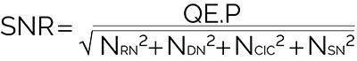
This function enables the performance of any conventional CCD to be assessed given the values for the key parameters – usually contained in the specification or performance sheets.
A number of points worth noting are:
Advanced detectors have been developed to extend sensitivity to the level of detecting a single photon. These systems amplify the initially detected signal using a multiplication process leading to an enhanced S/N at the read out of the CCD. The two main technologies are:
The degree by which a basic signal is amplified or multiplied is referred to as the gain factor. This can be selected through the software and leads to alteration of the voltages across the MCP in the case of the ICCD and the clocking voltages applied in the EM read out register of the EMCCD.
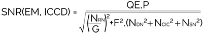
When an EMCCD or ICCD is being used an additional source of noise must be taken into account which is associated with the amplification process itself. This is the Noise Factor (F). For EMCCD cameras the noise factor is Ö2 or ~1.41. The noise factor in ICCDs depends on the type and quality of intensifier tube used: these can have values from ~1.6 to ~3.5. Taking the noise factor (F) and the actual or real gain (G) into account, the total noise for systems offering gain may be expressed as:

The SNR ratio for an EMCCD or ICCD may be written as:
When high performance systems are operated in a deep cooled low noise regime, where dark and spurious noise are negligible compared with the read out noise, this expression for the SNR may be simplified to:
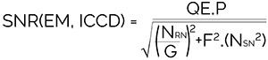
It can be seen here that by increasing the gain G, the term involving the read-out noise, NRN, becomes insignificant compared with the intrinsic shot noise of the signal, leading to ultra-sensitive detection capability. EMCCD and ICCD systems operated with appropriate configurations with sufficiently high gain can be used for single photon counting type experiments.
You can compare signal to noise for a range of cameras using the Signal to Noise Ratio & Noise Exposure Calculator.

© Oxford Instruments 2026
