
BC43 CF
View Product
 Part of the Oxford Instruments Group
Microscopes are an essential tool for modern life science applications. From medical diagnostics (for example, identifying the source of an infection, or the severity of a tumour) to food analysis. With such demand it is not surprising that in the last decade, there has been a boom in microscopy technologies allowing researchers to see beyond the diffraction limit of light and gain more insights into complex processes. However, ease of use and accessibility to high-end technologies are both difficult to find within a single product on the market.
With the evolution of microscopy systems, there has been a concurrent development in microscopy techniques. The first techniques in microscopy were based on Transmitted Light Microscopy. Additional techniques that are very valuable to modern microscopists are Widefield Fluorescence Microscopy and Confocal Microscopy. Furthermore, image reconstruction and treatment through photon reassignment is an essential factor in post imaging acquisition treatment. As such, Deconvolution software has become an essential tool for post-acquisition image treatment.
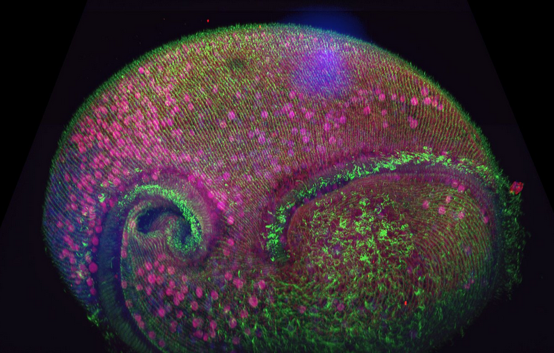
Figure 1 - Confocal volume of Stentor pyriformis imaged with Andor Dragonfly. 253 optical slices, captured with 40x (1.1 NA) water objective with 40 µm pinhole on Dragonfly. Courtesy of Victoria Yan, TU Dresden. Special thanks to Drs. Wallace Marshall and Vincent Boudreau and the Physiology course at MBL, Woods Hole.
In this article we will focus on an overview of microscopy acquisition and post-acquisition techniques and deliver a summary on Andor Microscopy systems solutions. Click on the buttons below to navigate directly to each microscopy topic and find out more.
In transmitted light microscopy, the light passes through the sample and, therefore, gives rise to the term "transmitted light microscopy".
The simplest technique is brightfield. This technique is useful to image thicker tissues or tissues stained with histological dyes such as haematoxylin and eosin stains to provide contrast and detail to the image. However, brightfield is not ideal for imaging samples that are thinner and unstained. The problem is that the structures inside the cells do not generate enough contrast to be visualised by our eyes. For this reason, other techniques of transmitted light microscopy techniques have evolved.
Phase-contrast microscopy uses phase plate rings in the optical path which generate higher phase differences between the structures within the samples, translating into a higher contrast image. Phase contrast is a great improvement on transmitted light microscopy, allowing the structure of thin unstained samples to be observed. Nevertheless, the problem with this technique is the bright halo generated (the "phase halo") that can hide detail.
Another transmitted light microscopy technique that delivers high contrast and high resolution is DIC. DIC stands for Differential Interference Contrast; it has complex and expensive optics. DIC relies on the use of two polarisers: one placed before the light hits the sample, and the other after the emitted light from the sample. The rays of polarised light will combine with a slight shift; this shift will generate the high contrast and high resolution of the DIC images. (learn more -Andor microscopy school – Transmitted Light Microscopy).
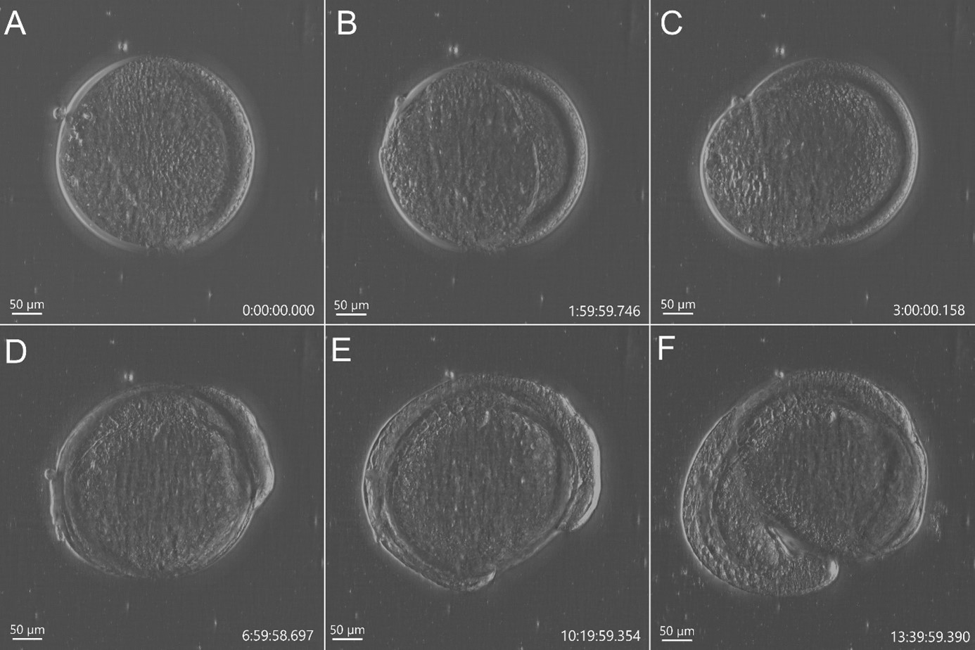
Figure 2 - Stain free imaging of Zebrafish development using DPC imaging modality from BC43. Single field image of live Zebrafish embryo image with BC43 using the 10x imaging objective (1,84 mm of field of view). Live embryo imaged from dome stage (A) until 17h ours post fertilization (F). Embryo at 50% (B) and 75% (C) epiboly, 3- (D) (E) somite stage. Zebrafish embryo was imaged with a 10X objective. Image is a maximum intensity projection of 35 stack, covering a full range of 700 µm, and captured every 20 min for 14 hours. Embryo was incubated at 28ºC. Image by Marco Campinho, Universidade do Algarve and Claudia Florindo, Andor Technology
A recent development in transmitted light microscopy is DPC – Differential Phase Contrast (Figure1). Andor has further developed DPC and implemented it in the new benchtop confocal microscope BC43 (patent pending).
DPC works using the principle that the gradient of phase can be extracted from a pair of intensity images taken with opposite illumination angles. Using a mathematical algorithm for DPC images, it is possible to have a quantitative phase reconstruction method for differential phase-contrast images. (Tian L. & Waller L., 2015).
DPC does not need:
Further, DPC allows constant access to the sample in all areas, all the time (not dependent on tweaking angles or adjusting polarisers). Unlike DIC, the DPC images can be obtained through plastic dishes, which is practical and indeed often essential for numerous biological imaging applications. DPC delivers high contrast and high-resolution imaging even in unstained thin samples (Movie 1).
In conclusion, DPC is an easy to use inexpensive, transmitted light microscopy technique that achieves large illumination angles and avoids the difficulties of mechanical scanning. For transmitted light microscopy, DPC combines the best of both phase contrast and DIC imaging techniques. Therefore, DPC is an excellent “label-free” imaging method with obvious applications in live sample imaging.
Movie 1 - Time lapse imaging of mammalian cells dividing on a TC culture plastic dish. 24 Well plate of mammalian cells expressing RFP-Cherry tubulin where imaged with DPC and fluorescent over 14h. The video starts by showing one position in detail and ends with all 24 wells, Cells were maintained at 37ºC in Co2 independent media. Note that the DPC gives optimal resolution through the plastic of the tissue culture plaque.
Andor’s Dragonfly and BC43 microscope systems both have transmitted light technologies available. The new benchtop confocal imager BC43, also benefits from having seamlessly integrated DPC into the system. Please read our technical article about BC43 to have a full grasp on the system and its transmitted light microscopy techniques
Widefield imaging is characterised by the full illumination of the sample and the subsequent detection of all emitted light from the sample. In practical terms, in widefield imaging, the detector will capture the in-focus light and the out of focus light.
Widefield fluorescence microscopy is an optical microscopy technique that, as above (in transmitted light microscopy techniques), captures all the light from the sample (in and out of focus). However, the basis of widefield fluorescence microscopy is the physical phenomenon of fluorescence:
The following steps can describe the phenomenon of fluorescence:
Fluorescence is an instantaneous phenomenon and ceases to exist as soon as the excitation light is turned off. Widefield fluorescence illumination can be achieved using mercury and xenon bulb LED light sources and, more recently, laser-based widefield illumination.
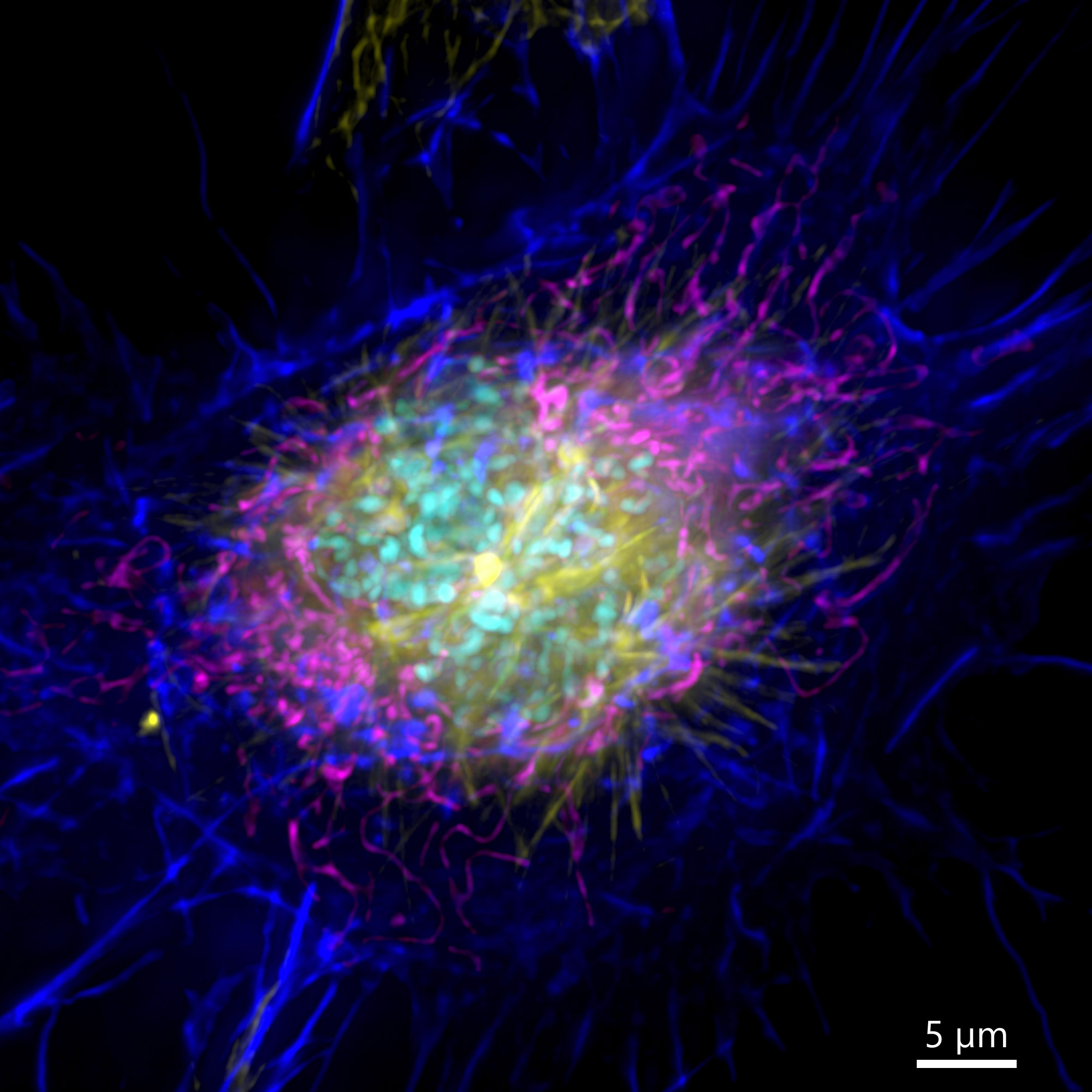
Figure 3 – Image of a mammalian cell acquired using widefield modality, using Andor BC43. Image shows the widefield image of a prophase cell ll. Image was further deconvolved after acquisition and is a Maximum intensity projection of 35 Stacks over a 7µm range. Dark blue-actin, magenta-mitochondria, yellow-microtubules, Cyan-DNA. Image by Claudia Florindo – Andor Technology.
Mercury-Arc lamps were the first light sources to be used in widefield fluorescence microscopy. One advantage of mercury bulbs is that the excitation wavelengths have several peaks that coincide with the excitation wavelengths of many of the common fluorophores used in microscopy (313, 334, 365, 405, 436, 546 and 579 nm). However, the illumination is not uniform across the whole spectrum, making it difficult to analyse samples quantitatively. Further, infrared and near infrared fluorochromes are not excited by this light source. Finally, mercury is a hazardous material best avoided if possible.
The Xenon-arc lamps have a much more uniform illumination across the visible spectrum compared to Mercury-Arc lamps However, the downside is the lower intensity of illumination, as well as the lower illumination power in the near UV/ UV range. This makes the use of common DNA staining dyes such as DAPI and Hoechst challenging using this light source as their emission is weak. In addition, these illumination sources (mercury and Xenon-arc lamps) suffer from a limited life span that is decreased if the illumination is switched on and off frequently.
LED light sources have established their place in fluorescence microscopy imaging. LEDs have evolved as a highly efficient illumination light source with a long-life span and in which the duration of the is not affected by switching on and off the system. In recent years LED light sources have become popular and replacing the once common Mercury and Xenon light sources.
Recently Andor has incorporated in its confocal systems, laser-based widefield imaging. Laser-based widefield imaging delivers sharp and precise illumination excitation, which consequently allows excitation of the sample fluorophores. Laser widefield imaging can deliver both controlled very low illumination intensities needed to image a highly sensitive sample, as well as the much higher laser powers required for higher end technological applications such as dSTORM super-resolution microscopy.
Movie 2 – Widefield imaging modality allows the capture of multiple channels on a sample for several hours without signs of phototoxicity or photobleaching.One hundred time points were acquired, every 8 min. For each time point we acquired and 3 channels and 15 Z planes. The experiment proceeded for over 10h. At the end of the experiment there was no signs of phototoxicity or photobleaching. (Magenta – Histone2BmCherry, cyan- Tubulin -GFP, Yellow- Sir actin). Image credits: Ines Baião-Santos and Álvaro Tavares and Claudia Florindo – Andor Technology.
Widefield microscopes also have bandpass filters that selectively allow the passage of the desired emission wavelengths to the detectors. In widefield microscopy, the detectors are cameras, generally EMCCDs or sCMOS. Go to Microscopy Cameras - Comparing Camera Technologies and Matching them to Applications to overview when to use the different imaging detectors available for widefield microscopy systems.
In summary, widefield systems capture all the light emitted from the sample and do not offer optical sectioning. For this reason, they are not suitable to image thick and highly scattering samples. However, as they capture all the light that is emitted from the sample, widefield systems are useful for:
Samples suited for widefield imaging are thin low scattering samples as bacteria, yeast, microalgae and monolayer cells. See Movie 2 and Figure 3 for examples of widefield imaging.
Andor confocal systems solutions Dragonfly and BC43 deliver laser-based widefield imaging.
Andor Dragonfly offers all the technological options in widefield imaging. From the most basic routine applications through to simultaneous dual colour imaging and even the high-end technological options which demand high laser powers such as dSTORM super-resolution.
Andor BC43 is the workhorse for routine research and applications requiring less specialised microscopy techniques. Still less demanding does not mean modest. With BC43 the user can acquire up to 4 different fluorescent imaging channels, meaning 4 different structures can be fluorescently labelled and detected with BC43.
Widefield fluorescence microscopy has its limits and visualizing samples with thicknesses greater than 30 µm is extremely hard in widefield microscopy and virtually impossible if the sample has thickness greater than 50 µm. The problem in widefield fluorescence microscopy is the out-of-focus light generated is captured by the detector and detail is lost. In these cases, the solution is to use some form of optical sectioning to restrict illumination to the in-focus area only. Optical sectioning can be achieved using confocal microscopes.
Confocal microscopes illuminate the sample by scanning the sample using one or more focused light beams and captures only the in-focus light from the optical section being imaged. There are two different types of confocal microscopes, Laser scanning confocal microscopes (LSCM) and spinning disk confocal microscopes. Both confocal imaging systems deliver optical sectioning through the sample, but the technology behind these two types of instruments is fundamentally different.
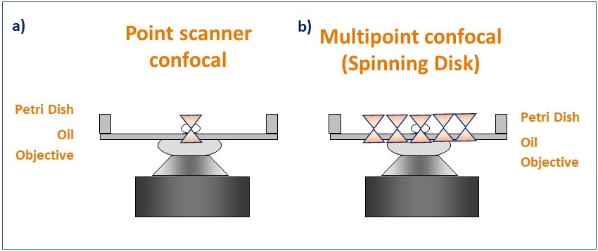
Figure 4. Schematic diagram illustrating the pattern of illumination for point scanner and spinning disk microscopy. Point scanner confocal microscopy (a) focuses a single point of laser light through a small aperture (pinhole) and scans sequentially across the sample point by point. Spinning disk confocal microscopy (b) illuminates the sample with a rotating pattern of 1,000's of pinholes for complete simultaneous confocal illumination.
Laser scanning confocal microscopes (also named Point scanner confocal Microscopes) scan the sample using a small spot of high-intensity laser light. The spot is focused using the objective and moves laterally along the scanning area to scan the sample. From the emitted light, only the in-focus Z section will pass through the single pinhole, to create the optical section (on that single spot). After passing through the pinhole, the emitted light is detected by a Photo Multiplier Tube (PMT). The resulting image is a sum of all the single points scanned in the scanning area.
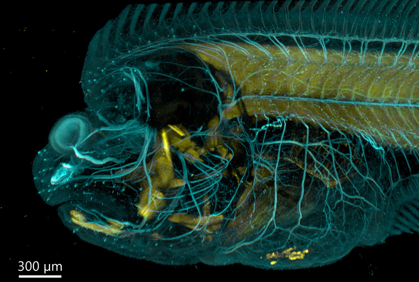
Figure 5 - Flat fish imaged with BC43 using confocal option. Image was acquired with Andor Bench Top Confocal – BC 43 using multiple tile acquisition and montage. 6 tiles were acquired to compose the image covering a range of 554 µm. Image rendered with Imaris (Image credits Marco Campinho, Universidade do Algarve and Claudia Florindo, Andor Techonolgy)
Limitations in Laser Scanning Confocal Microscopes include the dynamic range of the acquired image and the speed of acquisition (since the sample is scanned point by point). The PMTs have a quantum efficiency of 45%, meaning that from 100 excited photons, only 45 will be converted into electrons and detected as signal, the rest will be lost. Due to their slow speed of acquisition and lower quantum efficiency of the detectors, Laser scanning confocal systems are not suited to live imaging applications.
Importantly, due to the slow acquisition speed of point scanners, there is a need to compromise resolution when imaging large samples, which will deliver acquisitions with a resolution that is below the Nyquist criteria. Furthermore, even when compromising resolution, the acquisition speeds are extremely slow when compared to an optimized multipoint spinning disk system such as the Andor confocal systems.
An example of increased productivity is shown in (Movie 3). A chicken embryo of 1.2 mm was imaged acquiring 3 channels, 220 imaging planes and with 35 tiles. The full chicken embryo head resulted in 23 100 images that were acquired in only 2h. A comparative experiment was done with the same acquisition settings in a point scanner confocal system, and this image took 15h to be acquired.
Movie 3 – Optimized Multipoint confocal systems deliver optical sectioning up to mm inside a tick tissue. 1,2-millimetre depth cleared chicken embryo imaged in 2h with Andor Dragonfly. This video presents all the images acquired from a 1.2-millimetre chicken embryo head stage HH28. The full image 23 100 images took 2 hours to acquire with Andor Dragonfly and the same sample when image on a point scanner took 15 h to be imaged. Images were captured with Andor Dragonfly using a 10X objective and a 25 µm pinhole. The video is a result of 23,100 microscope images. Images were acquired with 3 independent fluorescent confocal channels, 35 tiles and each tile with 220 Z planes.
Spinning disk confocal microscopes, also known as multipoint confocal microscopes, scan the sample using a disk that contains multiple pinholes. The pinhole disk spins at high speeds, and less than a full disk spin is needed to deliver an image. This results in a system that can deliver optical sectioned confocal images as fast as 44 frames per second (Andor BC43) and 400 frames per second (ANDOR Dragonfly) (movie 4).
Andor´s spinning disk systems have a built in a dual microlens system in which the parallel rays of laser light are focused through an array of microlens, and the microlens are synchronized with the pinholes in the spinning disk. This dual system ensures better efficiency in light capture, reducing the background noise in the image. As a result, it reduces the laser power needed to achieve an excellent confocal image.
Movie 4 - In vivo imaging of blood flow in mouse intestine. Image acquired with with Andor Dragonfly at a 200 frames per second using Andor sCMOS camera. Sample courtesy of Dr. Takahiro Kuchimaru. (Jichi Medical University, Japan).
Further spinning disk confocal microscopes use camera-based detectors. Camera base detectors deliver a quantum efficiency that is up to 2x greater than Photo Multiplier Tubes (PMTs) quantum efficiency. In practical terms, to get the same signal to noise from an image in a laser scanning microscope, the sample needs to be illuminated with 2x more laser power when compared with an equivalent system using a camera-based detector. Note that increasing the laser power in sample illumination will result in more sample bleaching and phototoxicity.
Although the first generation of spinning disk confocal microscopes, delivered optical sectioning, it did not permit imaging deep within cells and tissues since the images would suffer from pinhole crosstalk around 30 µm depth. However, Andor Dragonfly and Andor BC43 have optimized pinhole spacing and size, which results in a system that can deliver optical sectioning deep inside cells and tissues, down to hundreds of nanometres and up to mm in depth.
In summary there are two types of confocal systems:
Both laser scanning and spinning disk confocal deliver optical sectioning increasing the signal to noise of an image and allow imaging deeper into cells and tissues compared to widefield systems.
Still, spinning disk systems deliver increased speed and productivity, enhanced signal to noise, and gentler imaging than point scanner confocal systems. For these reasons, currently spinning disk technology is becoming the technique of choice for many researchers.
When light passes through optical elements within any optical system (e.g. of a microscope), it suffers distortions. Any infinitesimal point will not appear as a single point, and it will emit light from the planes above and beyond the plane of focus which will cause the image to blur. This process is named convolution and is inherent to any optical system.
In a convoluted image, each point of the object is distorted. The distortion can be calculated using a mathematical function, the PSF (Point Spread Function). (Figure 6) The final image obtained is the result of the PSF applied to all the points on the object to be imaged.
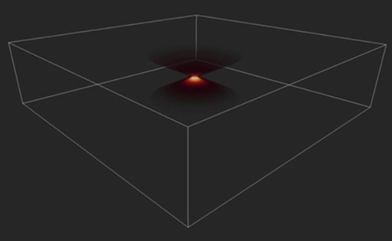
Figure 6 - Image of a PSF in 3D. Image shows the distortion of a single point imaged in an optical system, the Point Spread Function (PSF).
Although convolution is inherent to any optical system, compared to widefield systems, the resulting image from confocal systems is much less convoluted. Nevertheless, whatever system is used to acquire the image, there will always be convolution on the resulting image; the means there will always be distortion in the resulting images due to the optics. The more out-of-focus light is captured by the system, the more convoluted the resulting image will be. As such, the more out-of-focus light in the sample, the more blurred the resulting image will be.
As the mathematics of convolution is linear, thankfully the image of the object can be restored if the reverse operation to convolution is applied – this process is named deconvolution. In simple terms,
“Deconvolution algorithms revert the photons to the “place where they belong”,
delivering the real image of the object free from the distortions induced by the optical system.
Deconvolution algorithms work iteratively, increasing the image quality. The algorithm delivers the result when a pre-defined number of iterations or a pre-defined threshold increase in quality is reached. Unfortunately, this iterative process is time-consuming, requiring extreme resources from the CPU. The larger the image (large organisms, long time-lapse, etc.), the longer the processing time can extend, from many hours to days (depending on the data set).
Andor has implemented ClearView-GPUTM , in Fusion and Imaris our acquisition and image analysis software. ClearView-GPU is a GPU based deconvolution software. Andor´s ClearView-GPU deconvolution delivers results of up to 50x faster than CPU-based methods and up to 10x faster than other leading GPU-accelerated packages, especially for larger datasets, even when iteration acceleration is disabled.
Further, in both Dragonfly and BC43 , the deconvolution can be activated as part of the imaging protocol, speeding up the process and delivering a deconvolved image after the acquisition is finished.
There are two questions that arise from the above:
1- What are the advantages of using widefield imaging and deconvolving the image?
It is important to remember that one inherent aspect of increasing S/N in a confocal image is to perform optical sectioning by discarding out-of-focus light. Therefore, the images taken with a confocal microscope may require more illumination than when using a widefield system. This can result in higher bleaching and phototoxicity. One good option for a highly sensitive samples is to image in widefield modality. The resulting image can then be restored using deconvolution (Figure 7).
Because the sample was not very thick, the widefield modality was ideal to perform the imaging, the exposure time as well as the laser power used to acquire the image could be highly reduced.
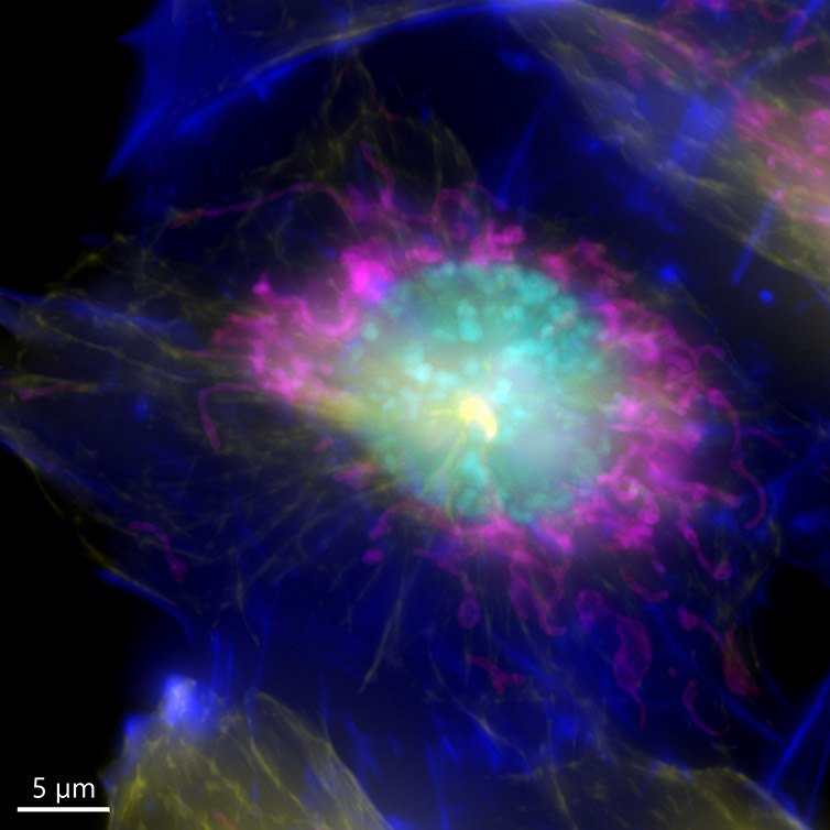
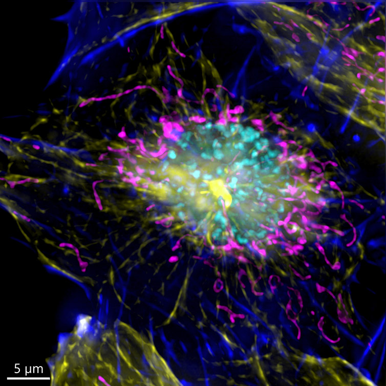
Figure 7 – Image of a mammalian cell acquired using widefield modality, using Andor BC43. Image shows the widefield image, before Deconfolution (left), and after deconvolution (right). Image is a Maximum intensity projection of 35 Stacks over a 7um range. Dark blue-actin, magenta-mitochondria, yellow-microtubules, Cyan-DNA. Image by Claudia Florindo - Andor Technology
2 - If with acquiring with widefield you can use less light and remove the blur with deconvolution; then why not always use widefield imaging?
As said above, both confocal imaging and widefield imaging benefit from image restoration by deconvolution. The user should decide the best imaging modality to acquire the data and then apply deconvolution to the resulting image. Figures 7 and 8 are good examples of it. In Figure 7, a mammalian cell Z stack image in the widefield mode benefited from deconvolution and delivered an excellent result. On the other hand, in Figure 8, one can observe a thick fish tail imaged in widefield modality and then deconvolved. In this case, it is clear that widefield is not the ideal imaging modality for this sample.
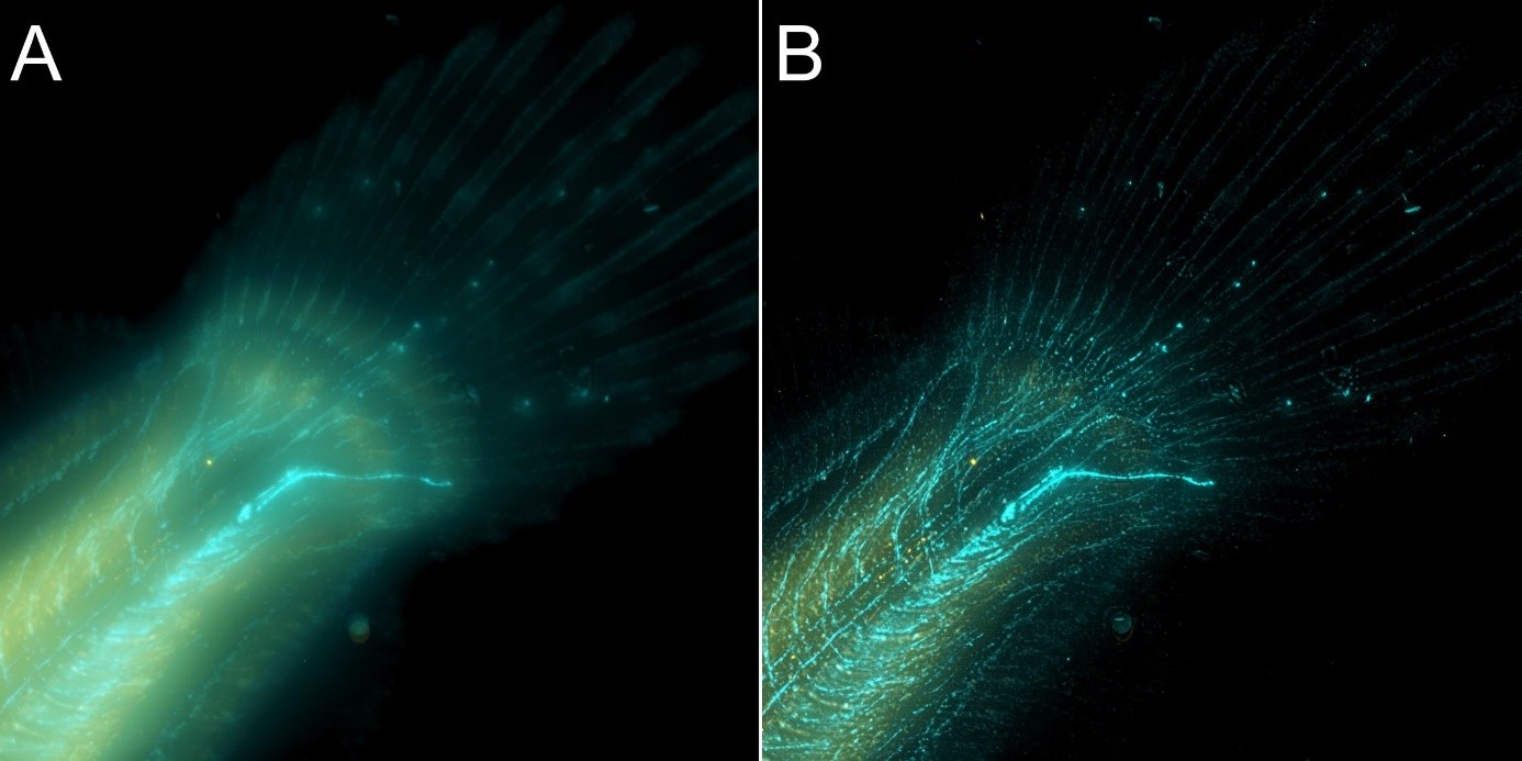
Figure 8 – Flat fish image in widefield mode using BC43 and deconvolved with Clear-View GPU based deconvolution. Flat fish tail, acquired with A) widefield imaging modality, and B) deconvolved. Widefield imaging modality is not the best option to image thicker samples – although the image benefited from restoration with Clear-View GPU based deconvolution, the original fish was too thick to be imaged in widefield modality. The result can be greatly improved if the original image is acquired using the confocal option. – see figure 9. Image by Marco Campinho, Universidade do Algarve and Claudia Florindo Andor Technology.
The same area of the fish from Figure 8 was also imaged in confocal modality, and subsequently deconvolved – Figure 9
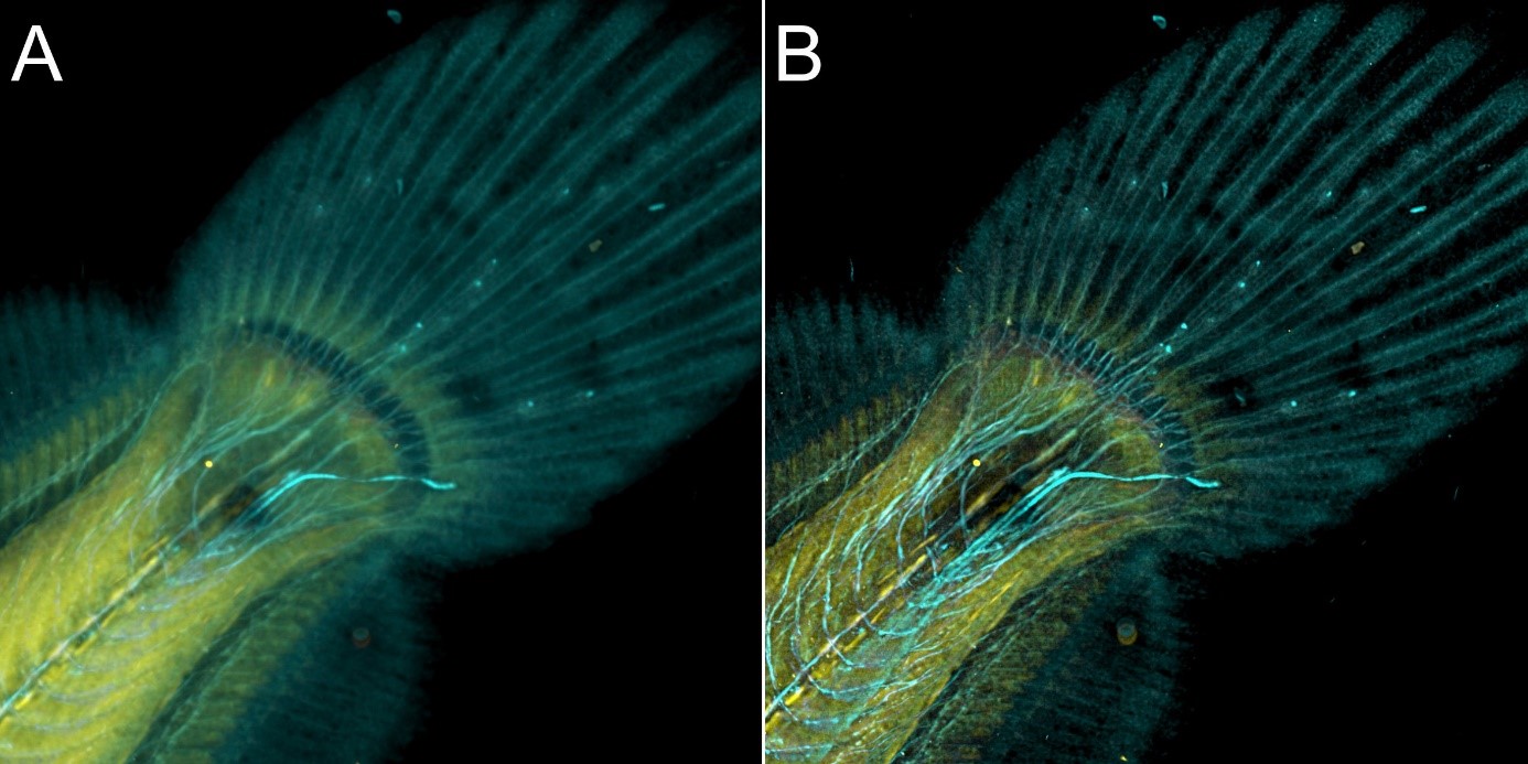
Figure 9 – Flat fish image in confocal mode using BC43 and deconvolved with Clear-View GPU based deconvolution. Flat fish tail, acquired with A) confocal imaging modality, and B) deconvolved. Confocal imaging modality is the best option to image thicker samples, the quality of the image was further improved with deconvolution with Clear-View GPU based deconvolution. Image by Marco Campinho, Universidade do Algarve and Claudia Florindo, Andor Technology.
Results presented in figures 7, 8 and 9 show a clear benefit from deconvolution, but as it can be observed for thicker samples (>30 µm) the spinning disk confocal instrument is required to remove the out-of-focus light and deliver an image that better represents the object.
Importantly, Andor confocals: BC43 and Dragonfly can image hundreds of micrometres up to the millimetre range, and Clear-View Deconvolution will always increase the signal to noise and resolution of the acquired images.
In summary, Deconvolution is the process by which the distortions of convolution in the optical system are mathematically corrected. As a result, it removes the blur and fog that the original image would have. Deconvolution, therefore, increases the SNR (signal to noise ratio) and resolution of the image. If a system provides deconvolution, then it is will always improve your image quality:
“ ...the application of deconvolution methods can always increase image quality, regardless of the source of the image...Deconvolve everything!”
Mark B. Cannell, Angus McMorland, and Christian Soeller, Handbook of Biological Confocal Microscopy, Chapter 25
Andor offers excellent confocal imaging systems adapted to the needs and applications of different users. Our proprietary technology in developing multipoint confocal microscopes ensure that with any of our systems, the users will benefit from:
We offer two confocal imaging systems, the BC43 and Dragonfly.
The BC43 is a high-quality price point confocal system. It is a "all in one" instrument, simple, compact and extremely user friendly. BC43 is a imaging workhorse that is ideal for multiple life sciences applications and that can fit in a corner of a core facility or on a laboratory bench. Learn more about BC43.
The Dragonfly is a high-end confocal system. Dragonfly is a complete imaging system suitable for the vast majority of life science applications; from more routine applications to high-end ultra-fast imaging, Dragonfly can deliver all.
Below we present two tables that may help you select the confocal that best suits the imaging needs
1- Microscope selection by application
2- Microscope selection by imaging technique
Please note that, the tables suggest which applications are most appropriate to different products. However, everyone's experimental requirements do vary, please talk to us about your specific requirements.
| Application Area | Type of Experiment | BC43 | Dragonfly 200 | Dragonfly 600 |
| Cell Biology | Intracellular Structure |  |
|
|
| Cell Cycle - Cell Division | |
|
|
|
| Mitochondria Imaging (fixed) | |
|
|
|
| Cytokinesis | |
|
|
|
| Mitochondria Imaging (live) |  |
|
|
|
| Early Embryo Development | |
|
|
|
| Microtubule Dynamics | |
|
|
|
| Intracellular Trafficking | |
|
|
|
| Expansion Microscopy | |
|
|
|
| Cilia Imaging (> 50 fps) |  |
|
|
|
| Single Molecule Live Imaging (not SMLM) expl RNA | |
|
|
|
| Chromatin Remodelling | |
|
|
|
| Vesicle Trafficking | |
 |
|
|
| Live Membrance Fusion Events | |
|
|
|
| Cell - Substrate Interaction | |
|
|
|
| Actin Polimerization Leading Edge of Cell Motility (TIRF) | |
|
|
|
| Ultra-Structure of Centrioles (SMLM) | |
|
|
|
| Nuclear Pore Complexes (SMLM) | |
|
|
|
| Ultra-Structure of Membranes (SMLM) | |
|
|
|
| Developmental Biology | ||||
| Limb Formation | |
|
|
|
| Tissue Sample Preparations | |
|
|
|
| Paraffin Sections | |
|
|
|
| Whole Organisms up to 500 µm Thick (depends on sample transparency) | |
|
|
|
| Organoids up to 500 µm Thick (depends on sample transparency) | |
|
|
|
| Whole Organisms 500+ µm Thick (depends on sample transparancy) | |
|
|
|
| Organoids 500+ µm Thick (depends on sample transparancy) | |
|
|
|
| Intracellular Trafficking | |
|
|
|
| Gene Expression in Development (with spacial biology) | |
|
|
|
| Fertilization | |
|
|
|
| Blood Flow Studies | |
|
|
|
| Pathogen-Host Interactions (fungus) | |
|
|
|
| Pathogen-Host Interactions (bacteria) | |
|
|
|
| Pathogen-Host Interactions (virus) | |
|
|
|
| Cancer Biology | Large Tissue Slices | |
|
|
| Live Imaging Cell Movement & Division | |
|
|
|
| Organoids up to 500 µm Thick (depends on sample transparency) | |
|
|
|
| In-Vitro Cell Invasion | |
|
|
|
| Organoids 500 µm + Thick (depends on sample transparency) | |
|
|
|
| Gene Expression in Cancer Cells (with spatial biology) | |
|
|
|
| Cell / Substrate Interaction and Adhesion | |
|
|
|
| Address Effectiveness of Small Molecule Inhibitors in Cancer Treatment (with TIRF) | |
|
|
|
| Actin Polimerization Leading Edge of Cancer Cell Motility (TIRF) | |
|
|
|
| Ultra-Structure of Centrioles (SMLM) | |
|
|
|
| Ultra-Structure of Cancer Cell Receptors (SMLM) | |
|
|
|
| Immunology & Diseases | Fixed Tissues | |
|
|
| Large Samples up to 500 µm Thick (depends on sample transparency) | |
|
|
|
| High Speed Live Imaging up to 40 fps | |
|
|
|
| Large samples 500+ µm Thick (depends on sample transparency) | |
|
|
|
| Gene Expression in Disease Cells (with spacial biology) | |
|
|
|
| High Speed Live Imaging > 40 fps | |
|
|
|
| Blood Flow | |
|
|
|
| Cell Surface Infection Dynamics - TIRF | |
|
|
|
| Mechanisms of Viral Infection | |
|
|
|
| Microbiology | Intracellular Structure (Super-Resolution SRRF-Stream) | |
|
|
| Intracellular Structure (SMLM) (Super - Resolution dSTORM) | |
|
|
|
| Intracellular Structure (SMLM) (Super - Resolution DNA-PAINT) | |
|
|
|
| Cell Surface Infection Dynamics - TIRF | |
|
|
|
| Mechanisms of Viral Infection | |
|
|
|
| Ultra-Structure of Bateria Cell Wall (SMLM) | |
|
|
|
| Ultra-Structure of Virus Capsid Complexes | |
|
|
|
| Neurobiology | Tissue Sectioning (live and fixed) | |
|
|
| Whole Brain Imaging up to 500 µm Thick (depends on sample transparency) | |
|
|
|
| Whole Brain Imaging 500+ µm Thick | |
|
|
|
| Map Brain Gene Expression (spatial genomics) | |
|
|
|
| Calcium Imaging (waves up to 40fps) | |
|
|
|
| Calcium Imaging (puffs, sparks > 40fps) | |
|
|
|
| Single Molecule Live Imaging (not SMLM) | |
|
|
|
| Growth Cone | |
|
|
|
| Receptor Localization & Recycling | |
|
|
|
| Live Vesicular Transport | |
|
|
|
| Extra Cellular Vesicles Fusion | |
|
|
|
| Visualize Receptors at the Cell Membrane | |
|
|
|
| Live cell Imaging of Synaptic Vesicles | |
|
|
|
| Live Cell Imaging of Neuronal Cell Membrane Fusion | |
|
|
|
| Resolve Tethered Synaptic Vesicles (SMLM) | |
|
|
|
| Resolve Synapses in 3D (30 nm axially)(SMLM) | |
|
|
|
| Biophysics | Protein-Protein Interactions | |
|
|
| Protein Membrane Dynamics | |
|
|
|
| Single Protein Transport | |
|
|
|
| Endo and Exocytosis | |
|
|
|
| Localization-Based Super Resolution | |
|
|
|
| Expansion Microscopy 1,2 | |
|
|
|
| Multiplex Imaging - Spatially resolved transcriptomics 2,3 | |
|
|
|
| Multiplex imaging - Spatially resolved proteomics 2,3 | |
|
|
|
- Not Suitable - Possible not recommended - Partially Suitable - RecommendedNotes:
| Technique/Technology | BC43 | Dragonfly 200 | Dragonfly 600 | |
| Imaging Modes | 2D Imaging | ✔ | ✔ | ✔ |
| 3D Imaging | ✔ | ✔ | ✔ | |
| 3D Tile Imaging | ✔ | ✔ | ✔ | |
| Deconvolution | ✔ | ✔ | ✔ | |
| Multi-well | ✔ | ✔ | ✔ | |
| Stitching | ✔ | ✔ | ✔ | |
| 3D Stitching | ✔ | ✔ | ✔ | |
| Finite Burst | ✘ | ✔ | ✔ | |
| 3D Finite Burst | ✘ | ✔ | ✔ | |
| Transmitted Light Microscopy | Differential Phase Contrast (DPC) | ✔ | ✘ | ✘ |
| Brightfield | ✔ | ✔ | ✔ | |
| Phase Contrast | ✘ | ✔ | ✔ | |
| Differential Interference Contrast (DIC) | ✘ | ✔ | ✔ | |
| Widefield Imaging | Up to 4 Channels | ✔ | ✔ | ✔ |
| More Than 4 Channels | ✘ | ✔ | ✔ | |
| Simultaneous Dual Camera Acquisition | ✘ | ✔ | ✔ | |
| Confocal Imaging | Single Pinhole Size | ✔ | ✔ | ✔ |
| Dual Pinhole Sizes | ✘ | ✔ | ✔ | |
| Simultaneous Dual Camera Acquisition | ✘ | ✔ | ✔ | |
| Up to 4 Channels | ✔ | ✔ | ✔ | |
| More Than 4 Channels | ✘ | ✔ | ✔ | |
| Confocal Imaging <500 µm* Thick | ✔ | ✔ | ✔ | |
| Confocal Imaging >500 µm* Thick | O | ✔ | ✔ | |
| Specialized Microscopy Applications | Compatible with Photostimulation Devices | ✘ | ✔ | ✔ |
| TIRF | ✘ | ✘ | ✔ | |
| dSTORM | ✘ | ✘ | ✔ | |
| 3D-STORM | ✘ | ✘ | ✔ | |
| DNA-PAINT | ✘ | ✘ | ✔ | |
| 3D - DNA-PAINT | ✘ | ✘ | ✔ | |
| SMLM (Simgle Molecule Localization Microscopy) | ✘ | ✘ | ✔ | |
| Detector Technology | sCMOS | ✔ | ✔ | ✔ |
| EMCCD | ✘ | ✔ | ✔ | |
| Other Specifications | NIR up to 780nm excitation | ✘ | ✔ | ✔ |
| Bench Top Instrument | ✔ | ✘ | ✘ | |
| Temperature Control | ✔ | ✔ | ✔ | |
| Multi-Position | ✔ | ✔ | ✔ | |
| Time Lapse Imaging | ✔ | ✔ | ✔ |
Key: ✔ - Possible, O - Might be Possible, ✘ - Not Possible
Bibliography

© Oxford Instruments 2026