Resources
 Part of the Oxford Instruments Group
Expand
Collapse
Part of the Oxford Instruments Group
Technical Article
Author: Andor
Published: 10 Feb 2021 · Last updated: 31 Jul 2025
In order to make a more detailed comparison between CCD, EMCCD and ICCD cameras we need to consider additional contributions to the camera's signal to noise ratio. This will help us to choose which camera is best for our experimental conditions.
The two primary additional effects are:
The first additional component is the Spurious Noise or Clock Induced Charge which originates from within the CCD camera. When charge is shifted pixel to pixel towards the output amplifier there is a very small but finite probability that charges can knock off additional charges by a process called impact ionization. These unwanted charges have the effect of generating an additional noise component.
The effect is present in all CCDs but in a good camera design the effect is usually minimized and can then only be seen in exceptional circumstances, for example when binning a very large number of pixels. In a CCD camera or an ICCD camera the noise component is so low it typically is hidden by the readout noise or dark current components. In an EMCCD however, spurious charges that occur in the image section are amplified by the EMCCD gain register and therefore are very detectable. Incidentally the EMCCD gain register works by effectively harnessing the same effect of impact ionization that creates the spurious charges.
The second noise component originates from the amplification process and is represented by the Noise factor. In any amplification process when a signal is amplified, the input noise is also amplified. However the amplification can add additional noise and this noise must be taken into consideration.
Overall the following equation can be derived for the total signal to noise ratio. It is important to consider how this affects the camera. We can do this by comparing values in a table and on a graph.
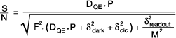
If we examine the theoretical signal to noise ratios for various cameras using this equation we can appreciate the comparisons between the cameras. The parameters we have used are as follows:
| Ideal | CCD | EMCCD | ICCD | |
| Quantum Efficiency (DQE) | 100% | 93% | 93% | 50% |
| Readout Noise | 0 | 10 | 60 | 20 |
| Gain (M) | 1 | 1 | 1000 | 1000 |
| Spurious Noise | 0 | 0.05 | 0.005 | 0 |
| Dark Noise | 0 | 0.001 | 0.001 | 0.001 |
| Noise Factor (F) | 1 | 1 | 1.41 | 1.6 |
Note the Noise Factor for an EMCCD is 1.41 which is exactly the theoretical predictions of an ideal gain register with a stochastic gain process as used in the EMCCD. The Noise factor for a Filmless Gen III ICCD has been measured as 1.6 which is better than their filmed counterparts which have a Noise factor of 3.52.
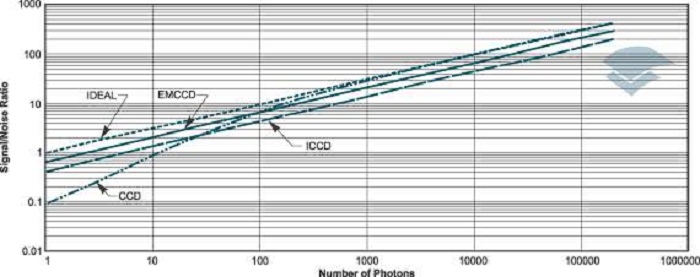
The results are displayed in Figure 1. As you can see in the limit of low photon signals and low signal to noise ratios the gain of the EMCCD and the ICCD have the higher sensitivity and can achieve detection (S/N > 1) at light levels less than 10 photons per pixel. As the readout of the EMCCD and ICCD can also be significantly faster, this means that a signal can be detected up to 10-100 times faster with an EMCCD or an ICCD than a slow scan CCD.
In integrating mode the EMCCD outperforms the ICCD with the higher quantum efficiency and the lower Noise factor. At higher signal to noise ratios and with more photons of light, the CCD starts to outperform the EMCCD and ICCD. The near perfect noise factor of 1 and with the ultimate in quantum efficiency the CCD starts to rapidly approach the performance of the ideal detector. The EMCCD can of course be switched into a regular CCD by lowering the Gain to unity and reading out slowly to achieve the similar performance.
In the limit of very low signals where there is less than 1 photon per pixel per readout the EMCCD and ICCD can be used in the photon counting mode unlike the CCD. The higher quantum efficiency usually enables the EMCCD to outperform the ICCD but in some circumstances the ICCD can outperform the EMCCD if the ICCD intensifier has lower EBI (Equivalent Background Illumination) than the Clock Induced Charge noise of an un-optimized EMCCD. In the limit of very low signals you can see the CCD's S/N suffers due to the fixed Readout noise component and this continues until the photon flux level is greater than the readout noise squared. The EMCCD and ICCD work well for low light levels as the Gain effectively removes all the read out noise component of the noise.
A note of caution, the gain components in an ICCD and an EMCCD i.e. the MCP (Micro Channel Plate) and the EM register (Electron Multiplication), suffer from gain aging effects. For a given applied voltage to the gain components, you would expect the gain to remain constant. However, the gain components suffer from parasitic effects which lower their gain as a function of the total charge extracted from them. Therefore, if you measure the gain over a period of time at a fixed voltage and temperature the gain will fall off and the fall off will be more pronounced the more extracted charge that passes though the gain component.
The gain is not lost however and a certain gain can be recovered by simply increasing the voltage in the gain component to compensate for the aging effect. Ultimately the gain components can be damaged by excessive voltage so they do have an ultimate lifetime. To minimize the effects of gain aging it is desirable not to have the gain turned up when the device is not recording signal and to use the gain sparingly i.e. set the gain to give you sufficient sensitivity and not to use the gain at the maximum level needlessly. Please refer to the more detailed notes in your manual on gain aging effects.
Intensified CCDs also suffer from an additional aging effect due to the poisoning of the photocathode. The photocathode gets damaged by contaminates in the image intensifier tube and this damage is accelerated when the tube is gated on. Improving production techniques has reduced the level of contaminates and hence increased the tube lifetime. The damage is not recoverable so, again, it is good practice to keep the gain turned down when it is not required and minimise the light falling on the photocathode.
Explore our related assets below...

© Oxford Instruments 2026
