Resources
 Part of the Oxford Instruments Group
Expand
Collapse
 Part of the Oxford Instruments Group
Adoption of wavefront sensing instrumentation is increasing at optical and near-infrared ground-based observatories of all scales and configurations as a critical component of adaptive optics systems that push the performance of telescopes toward their theoretical limit. The sizes, designs, ages, instruments, and science applications of each observatory can vary significantly, however, and their requirements from a wavefront sensing camera are equally diverse in terms of frame rate, field of view, and wavelength coverage. To meet the varied wavefront sensing needs of the astronomical community, robust high-speed low-noise cameras have been developed in a range of formats based on multiple remote sensing technologies. EMCCD and sCMOS sensors are installed in the fastest and most sensitive optical wavefront sensing cameras, while the integration of InGaAs and e-MCT sensors has introduced extremely high-performance wavefront sensing capability at near-infrared wavelengths. In its many forms, wavefront sensing instrumentation is routinely aiding delivery of increased spatial resolution and signal-to-noise ratio in astronomical imaging, spectroscopy, and interferometry at telescopes with apertures >1 m.
Light waves emitted or reflected by an astronomical object are effectively parallel when they reach the top of the Earth’s atmosphere; at this point they form a planar wavefront. The time-variable density of Earth’s turbulent atmosphere refracts light to varying degrees across the wavefront as it propagates toward the ground, causing small deflections in the light’s direction across the wavefront that result in deviations of the location where it ultimately focuses on an observatory’s science detector. In this way, the atmosphere smears out images of astronomical sources and prevents observatories from reaching their peak theoretical sensitivity and spatial resolution.
Many observatories operating telescopes with apertures >1 m are now developing adaptive optics (AO) systems to mitigate atmospheric wavefront distortion. Critical components of AO systems include sensitive high-speed wavefront sensing (WFS) cameras to record the varying shape of the distorted wavefront as input to AO control and wavefront correction systems.
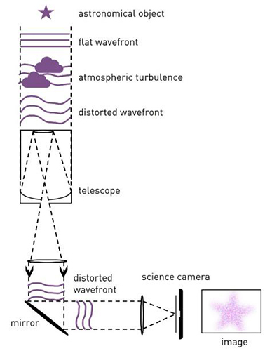
Figure 1 – Simplified diagram of atmospheric wavefront distortion in astronomical observations.
The wavefront is focused by an array of microlenses into a corresponding array of spots on the WFS detector. Wavefront distortions are encoded in the relative positions and separations of the spots.
+ Good throughput, supporting use of fainter guide stars or higher time resolution.
+ S-H WFS instrumentation is relatively simple.
- Accurate spot position measurement requires multiple pixels per spot, potentially limiting measurements to lower spatial frequencies.
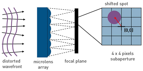
Figure 2 – Simplified diagram of a Shack-Hartmann WFS.
The distorted wavefront is constructively interfered with a reference wavefront, or a spatially filtered copy of itself. Wavefront distortions are encoded in the amplitude of the fringes in an interferogram.
+ High spatial resolution is possible, enabling measurement of high frequency spatial modes.
- Instrumentation setup may be complex and sensitive to alignment precision.
- Photon counts may be very low, requiring an extremely sensitive detector.
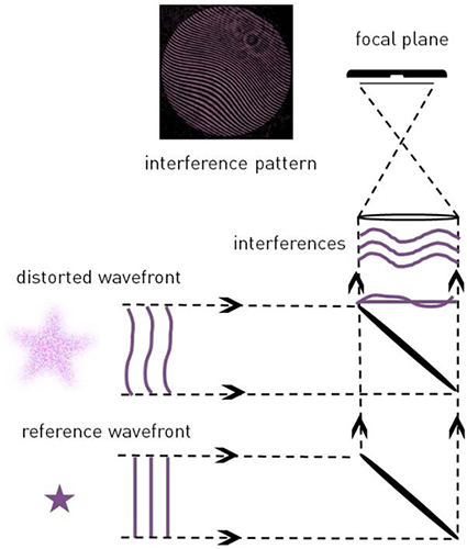
Figure 3 – Simple diagram of a Fizeau interferometer.
Akin to a 2D Foucault knife edge test, observed light is split into four with a four-sided (pyramid shaped) prism to produce four images of the telescope pupil. Wavefront distortions are encoded in the intensity distribution of matching parts each pupil image.
+ Very high throughput, supporting use of faint guide stars and high time resolution.
- Limited spatial dynamic range without compromising WFS mechanical simplicity (prism oscillation) or sensitivity (beam diffusion).
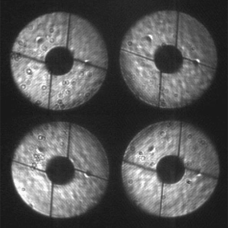
Figure 4 – The Subaru telescope pupil imaged with OCAM2K and a pyramid wavefront sensor. Courtesy of NAOJ/SCExAO.
Each WFS technique brings different capabilities, benefits, and limitations to each type of astronomical observation. How do we choose an appropriate wavefront sensing camera?
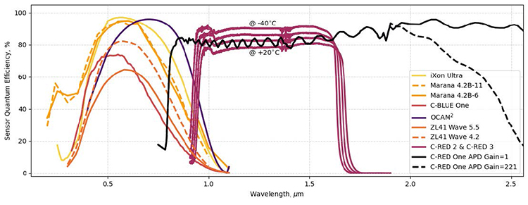
Figure 5 – Quantum Efficiency (QE) curves measured for sensors integrated into Andor and FLI cameras commonly used for wavefront sensing. Sensor QEs for iXon, Marana and ZL41 cameras are measured at ambient temperatures. OCAM2 sensor QE is measured at -40ºC. C-RED 2 & C-RED 3 sensor QEs are measured in 20ºC temperature increments between -40ºC and +20ºC. C-RED One sensor QE curves are digitized from Fig. 9 of Finger et al. (2023).
WFS cameras are built with a variety of formats, sensor technologies, and readout architectures. Andor and First Light Imaging together provide a range of 12 cameras that can be used for WFS, each based on one of four sensor types (see Table 1). As shown in Fig. 5, these diverse cameras provide sensitivity across a range of optical and near-infrared wavelengths.
| Camera Sensor Type | Sensor Formats (Array @ Pixel Pitch) |
| CB1 CMOS |
7.1MP
3216x2232 @ 4.5 μm
|
|
1.7MP
1608x1136 @ 9.0 μm
|
|
|
0.5 MP
816x656 @ 9.0 μm
|
|
| C-RED ONE e-APD/MCT |
320x256 @ 24.0 μm
|
| C-RED 2 & 3 InGaAs |
640x512 @ 15.0 μm
|
| iXon Ultra EMCCD |
888
1024x1024 @ 13.0 μm
|
|
897
512x512 @ 16.0 μm
|
|
| Marana CMOS |
4.2B-11
2048x2048 @ 11.0 μm
|
|
4.2B-6
2048x2048 @ 6.5 μm
|
|
| OCAM2 EMCCD |
240x240 @ 24.0 μm
|
| ZL41 Wave CMOS |
5.5
2560x2160 @ 6.5 μm
|
|
4.2
2048x2048 @ 6.5 μm
|
Table 1 – Sensor formats of Andor and First Light Imaging wavefront sensing cameras.

Figure 6 – Nominal peak frame rates of Andor and First Light Imaging wavefront sensing cameras when reading full unbinned frames. These rates may be increased by binning and/or cropping the sensor. Frame rate may also be decreased for better sensitivity. Units are frames/sec.
There are three main factors to consider when choosing a camera for WFS:
Sensitivity - A WFS camera should have high quantum efficiency (QE) at the wavelengths available for WFS (i.e. not used for science; see Fig. 5). This requirement may determine the choice of sensor technology (Table 1). Equally important is the minimisation of noise in WFS data. At the high frame rates used in WFS (see Fig. 6), a camera operates in the read-noise dominated regime. The best WFS cameras have very low read noise <<3 e-. Some WFS cameras use electron multiplication (EMCCD, e-APD) technology to boost detected signal over the read noise floor.
Speed – WFS cameras need to run at frame rates high enough to accurately record rapid variations in atmospheric turbulence, typically at hundreds to thousands of frames/second (see Figure 6).
Spatial Resolution – A WFS camera’s spatial resolution determines its ability to resolve the spatial frequencies that make up a wavefront. A higher resolution camera, with more and/or smaller pixels, will be able to capture a more accurate picture of a wavefront’s shape, enabling more accurate wavefront correction.
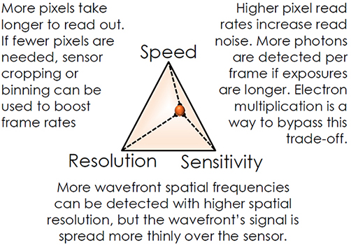
Figure 7 - Wavefront Sensing trade-offs. It’s often true that we can’t have everything at once. Sometimes it may be necessary to sacrifice camera speed, sensitivity, or resolution to boost its wavefront sensing performance in other respects.
Date: October 2024
Author: Tom Seccull
Category: Application Note
