Resources
 Part of the Oxford Instruments Group
Expand
Collapse
Part of the Oxford Instruments Group
Application Notes
Author: Cecile Brun
Published: 01 May 2023 · Last updated: 29 Jul 2025
Tags: wavefront-sensors-app, swir-cameras-ps, swir-adaptive-optics
Light propagating through the atmosphere is disturbed by turbulences. Real-time correction systems, known as Adaptive Optics loops, use the detected light wavefront and deformable mirrors to compensate for the distortions. They are a key element for astronomical observations and Free-Space Optical communication systems.
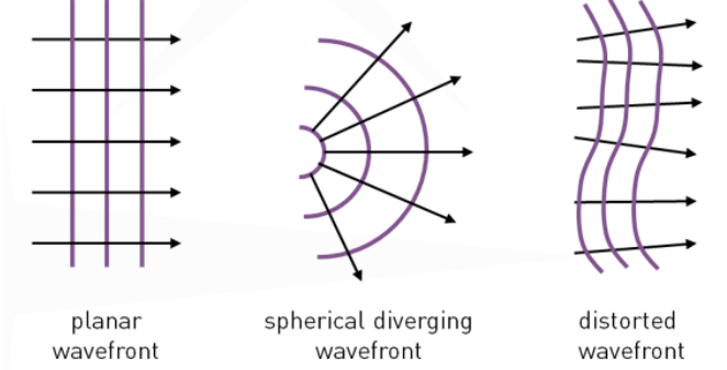
Light propagates as a wave. The set of spatial points that the wave has taken a given time to reach is called a wavefront. A wavefront (purple lines) propagates in a direction normal to its surface (black arrows).
When propagating in an ideal media, wavefronts will be planar or spherical. Distortions from a perfect wavefront arise when light propagates in a turbulent media, such as the atmosphere.
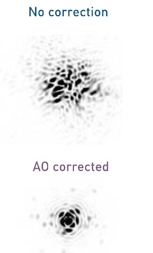
In astronomy, atmospheric distortions limit the resolution of telescopes (e.g. on the left). In Free Space Optical communications, the distortion expands the laser beam (e.g. on the right), preventing efficient coupling in the optical fiber network in the Ground Station.
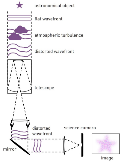
 The wavefront measurement can be used to account for the distortions using a method referred to as adaptive optics. This enables to retrieve the information (e.g. the star) prior to the distortion caused by propagation in a turbulent media (e.g. the atmosphere).
The user may also be interested in studying the media which is causing the wavefront distortion. For example in weather / environmental science, material inspection, quantitative phase imaging in biology, etc.
Wavefront sensors are camera-based devices, able to measure the distortion of the wavefront. To be able to map a wavefront accurately, they must be able to make a snapshot image of the turbulence. Hence camera speed must be sufficient for accurate temporal sampling of the distortions.
Wavefront sensing aims to make an instantaneous picture of the incident optical wavefront.
Traditional wavefront sensors could be divided into two categories. The first one is based on geometrical optics, with the Shack-Hartmann Wavefront Sensor (SHWFS) being the most frequent design. The second category is based on diffractive optics, with the phase information being encoded into interferometric fringes.
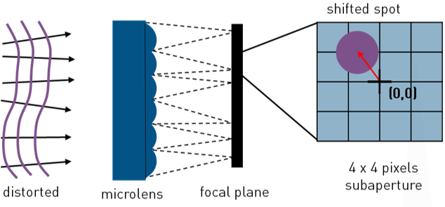
In a Shack-Hartmann Wavefront Sensor, the camera is placed in the focal plane of an array of microlenses, either directly (as illustrated) or using a relay lens to re-image the focal plane.
The incoming wavefront is focalized onto the camera at each subaperture (microlens area) position. The average phase slope can be retrieved from the focal spot position.
For high phase accuracy, many pixels are required per microlens to precisely localize the spot (4 x 4 on the example below).
Shack-Hartmann Wavefront Sensor
Interferometry is a technique making use of the physical interference phenomenon. This phenomenon is the result of the interaction of several light waves combining to form a resulting, different light wave. An interference pattern can be observed in a plane transverse to the light propagation direction.
The wavefront information can be retrieved from the interference pattern using physical models. To enable accurate wavefront reconstruction, the pattern must be imaged with high spatial resolution and signal-to-noise ratio.
In an interferometer, the light is split into two beams which travel different optical paths and are then combined to produce an interference pattern. The interference pattern will contain information about any deviation between the reference beam and the distorted beam.
Various optical schemes exist: for example, in a Michelson interferometer the beams combine in the pupil plane, while in a Fizeau interferometer they combine in the image plane.
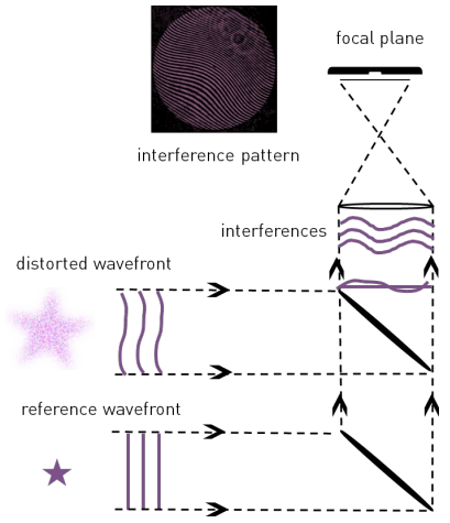
Simplified scheme of a Fizeau interferometer
Geometrical optics and interferometry are the main wavefront sensing techniques. Multiple methods, offering different compromises in terms of performance, cost and ease of integration, are derived from them.
Wavefront sensors are at the heart of adaptive optics systems. Adaptive Optics (AO) aim to account for wavefront deformations in real-time.
The idea of accounting for the atmospheric turbulences in real time for astronomy was firstly introduced by Babbock as early as 1953 [1]. With the progress of wavefront sensors, deformable mirrors and real time computers, AO systems have become very popular and relatively straightforward to produce. The figure below illustrates the working principle of the close-loop approach.
The wavefront from a distant object is distorted by the atmosphere. The wavefront sensor measures the deviation with regards to the undistorted wave, providing inputs for the control system which commands the deformable mirrors. The deformable mirrors then compensate the distortions. The corrected beam is sent to the science camera for imaging. By continuously measuring and correcting wavefront errors, the adaptive optics system is able to produce much sharper and clearer images than would normally be possible. While the wavefront sensor operates at very high speeds, the science camera can integrate over long exposure times.
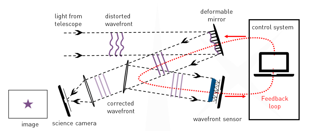
Simplified schematic of the Adaptive Optics close-loop approach.
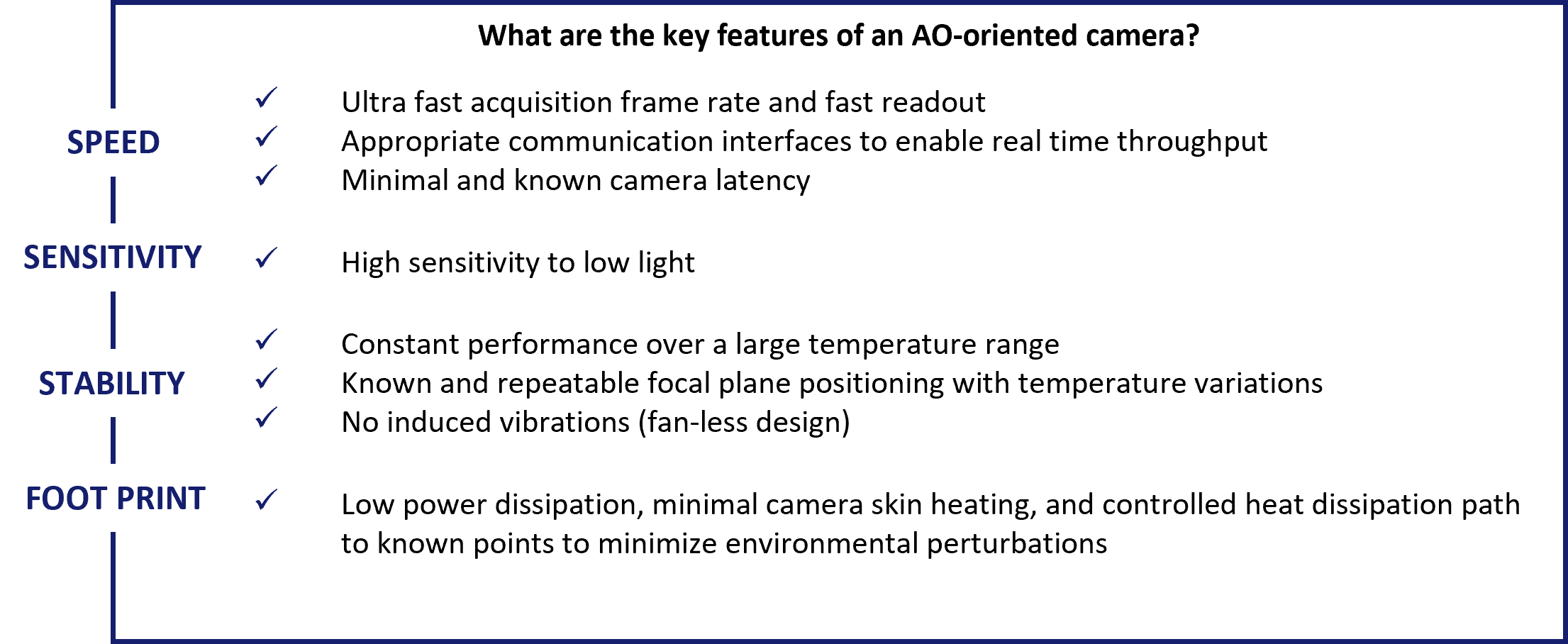
The performance of an AO system depends on the sampling, wavelength range and correction quality of the wavefront error in both spatial and time domains. Therefore, the cameras used in AO systems and their ability to provide an instantaneous and real-time image of the wavefront perturbations are a key contribution to the overall system performance.
First Light Imaging designs cameras with adaptive optics requirements in mind!
Over the years, multiple scientific papers using First Light Imaging cameras as wavefront sensors have been published. Here are a few use cases.
With a primary mirror of 6.5 m, the Magellan Clay telescope at the Las Campanas Observatory in Chili is one of the largest telescopes in the world. MagAO-X is an adaptive optics system designed for this telescope to achieve high-contrast imaging of growing young planets (accreting protoplanets) at the Hα line (656 nm).
The MagAO-X uses a Pyramid WaveFront Sensor [4]. This alternative to the Shack-Hartmann consists of a pyramid, a camera lens, and an OCAM²K EMCCD camera.
The pyramid itself is made up of two four-sided prisms aligned back to back that split the incoming beam into four separate beams. The subapertures are imaged in the detector plane. At each subaperture, the phase information can be retrieved from the intensity image. Dedicated to astronomical wavefront sensing applications, the OCAM integrates the CCD220 sensor, a Peltier-cooled 240 x 240 pixel frame-transfer 8-output back-illuminated sensor [2].
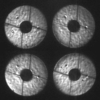
Image of a pupil with Pyramid wavefront sensor. 3.5 kHz binned framerate and 0.3 e- readout noise at a gain of 600x. Courtesy of NAOJ / SCExAO
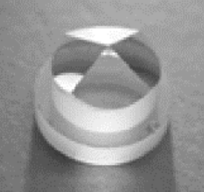
One four sided prism.Courtesy of Paolo Stefanini
The adaptive optics systems for future Extremely Large Telescopes will be assisted with Laser Guide Stars (LGS). Researchers at the NRC’s Herzberg Astronomy and Astrophysics Research Centre have developed an experimental adaptive optics system : REVOLT, short for Research, Experiment and Validation of Adaptive Optics with a Legacy Telescope [5]. The aim is both to test adaptive optics technologies and provide AO-corrected light to other experimental instrumentation technologies.
The long elongation of LGS spots on the sub-pupils far apart from the laser beam axis constraints the design of wavefront sensors. They must be able to fully sample the elongated spots without under-sampling the non-elongated spots [7].
The adaptive optics system is based on a Shack Hartmann wavefront sensor: 16 x 16 lenslet array with a 13’’ field of view in each lenslet. A CB1 1.7 Mp camera [6] is integrated in the system. It uses a 352 x 352 region of interest, operating the camera successfully at 1.18 kHz.
The image on the left shows REVOLT improved the resolution by a factor of 5 and the sensitivity by a factor of almost 500.
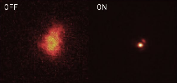
Image of the star Alpha Persei with the AO system off (left) and on (right). Courtesy of NRC.
The first generation of adaptive optics are getting upgraded with larger numbers of actuators, faster low-noise detectors and more sensitive wavefront sensors.
The Subaru Telescope is located at Mauna Kea, Hawaii. With a primary mirror of 8.2 m in diameter, it is one of the largest telescopes in the world. The telescope is equipped with a wide range of instruments, including a near infra-red pyramid Wavefront Sensor [8], which is designed to work between 0.98 µm (y-band) and 1.8 µm (H-band). This instrument provides images to the Subaru Coronagraphic Extreme Adaptive Optics (SCExAO).
The star light is collimated and the pupil reimaged on a fast tip/tilt modulator, then it is refocused on the tip of a double-roof prism pyramid optics. Finally, a pupil lens reimages the four pupils on a fast camera.
The camera used for the wavefront sensing is the C-RED One camera. It enables controlling a 64 x 64 actuators deformable mirror at up to 1.6 kHz. The camera is used in Correlated Double Sampling mode with a sub-frame of 160 x 160 pixels and operates at 2 kHz.
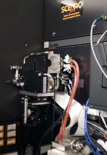
C-RED One sticking out of AO188, with SCExAO on its right. Courtesy of NAOJ / SCExAO.
SPIDERS is the acronym of Subaru Pathfinder Instrument for Detecting Exoplanets & Retrieving Spectra [9]. This instrument is intended for the Subaru Telescope, located at the Mauna Kea Observatory on the island of Hawaii. The instrument is designed at the National Research Council of Canada (NRC). The goal is to demonstrate new focal-plane wavefront sensing techniques.
A C-RED 2 camera [10, p. 2] is integrated in the Fast Atmospheric Self-Coherent-Camera (SCC) [11] to perform focalplane wavefront sensing for the science images. FAST relies on the method of recording coronagraphic images on millisecond timescales, freezing the dynamic nature of temporal aberrations in individual frames. When imaging through a coronagraph, the light from the star central region is blocked, revealing the surrounding fainter features.
In the optical bench, the light coming from the telescope is split into two beams. One is spatially filtered and used as a reference. Then, the two beams are recombined in the focal plane in a Fizeau scheme. The Fizeau image in the focal plane will show fringes pinning the intensity distribution of the solar flux.
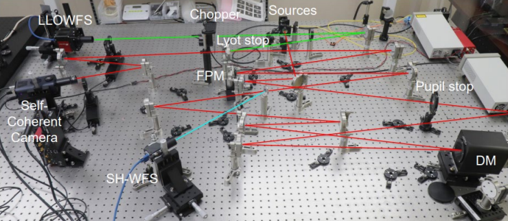
FAST optical test bench integrating the C-RED 2. Courtesy of NRC.
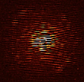
Blinking fringed PSF, as imaged with the C-RED 2 camera in the FAST concept. Courtesy of NRC.
Atmospheric turbulences limit the achievable bandwidth in free-space optical communications and the observational precision in ground-based optical astronomy.
Precise knowledge of the turbulences can be used to select the best sites to install ground stations for observation and communication.
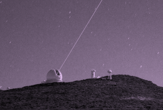
The 24-hour Shack-Hartmann Image Motion Monitor (24hSHIMM) is an instrument designed for continuous estimation of turbulence through the use of wavefront sensing. It has been developed at Durham University [12].
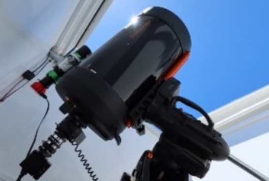
Photo of the 24hSHIMM operating during daytime on La Palma, Spain. Courtesy of Durham University.
The wavefront sensor is a C-RED 3 camera [13] combined to 500 µm-pitch square lenslet array. The collimating lens and the microlens array can produce six sub-apertures 4.7 cm wide across the pupil. This configuration ensures proper sampling of the focal spots.
The wavefront sensor runs on a 224 by 224 pixel sub-region at short integration time of 2 ms to ensure snapshot images of the turbulence.
The compact C-RED 3 is an ideal candidate for this use case, as cooling is not necessary at short integration times. For more information, you can refer to the dedicated white paper.
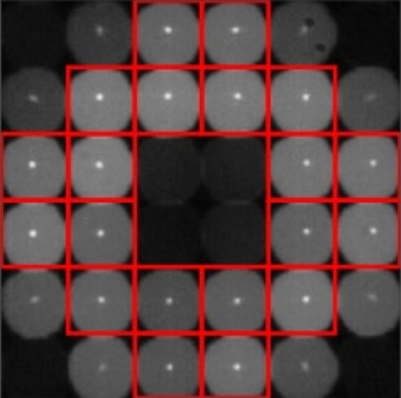
A typical WFS frame from the 24hSHIMM The red squares indicate the subaperture focal spots used for data analysis. Courtesy of Durham University.
First Light Imaging cameras, both in the visible range (OCAM² and CB1) and in the short-wave infrared range (C-RED One, C-RED 2, C-RED 2 Lite and C-RED 3) are used to enhance the performance of wavefront sensors and adaptive optics loops.
First Light Imaging cameras were designed for adaptive optics applications. They are optimized for high speed and low noise operation. Their design allows precise temperature monitoring, with no induced vibrations, to ensure stable focal plan positioning. Heat dissipation is controlled so as to minimize the perturbation on the surrounding environment. Communication interfaces have been chosen to optimize latency, data throughput and distance.
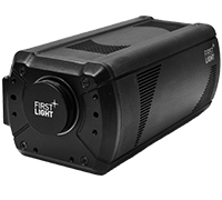
The OCAM was the first camera dedicated to astronomical wavefront sensing applications to reach sub electron readout noise [2] and is still going strong! Today, two versions exist : OCAM²S (shuttered) and OCAM²K (unshuttered), with a wavefront sensor.
In the visible range, AO developments are focused on optimizing resolution, as spot elongation from Laser Guide Star Shack Hartmann wavefront sensor requires an increase of the pixel format. The CB1 camera was designed to address this challenge.
Without any competitor, this incredible camera has its place in the extreme adaptive optics systems to operate them at unprecedented speeds!
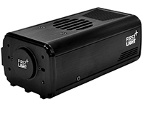
Thanks to its high performance at both short and long integration times, the C-RED 2 camera is a great tool for research laboratory developments.
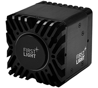
In Free Space Optical communications, the 1550 nm wavelength has imposed itself as the de-facto choice. AO is to compensate for beam spatial spreading [3]. The uncooled C-RED 3 is an ideal candidate for such use cases.
Wavefronts describe the propagation of a light wave beam. Wavefronts, in ideal media, will be planar or circular. When imaging of turbulences – whether they arise from the atmosphere, a tissue, imperfect optical elements, etc.
The wavefront information can be used to characterize the media inducing the turbulences as well as input information for adaptive optics loops. The purpose of adaptive optics is to account for the turbulence and enable high resolution imaging across turbulent media.
For telescopes ranging from large (8 to 40 m) all the way to small (1-2 m), adaptive optics improves image quality and stability. In Free Space Optical Communications, adaptive optics can be used for uplink laser beam pre-compensation prior to atmospheric distortion. Other applications of wavefront sensing include, but are not limited to, quantitative phase imaging in biology, the study of surface defects in optics, etc.
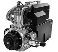
First Light Imaging develops and manufactures cameras for wavefront sensing applications and adaptive optics systems. In the visible range, the OCAM² camera is a proven product, with an established track record in adaptive optics for astronomical imaging in the world’s largest telescopes. The CB1 camera, based on sCMOS sensors is an affordable alternative, offering a great compromise between the larger number of pixels required in Laser Guide Star wavefront sensing and sensor sensitivity. In the short-wave infrared range, the C-RED One camera is the solution for extreme adaptive optics. With unprecedented sensitivity performances, it opens new horizons in astronomical imaging.
For applications such as Free Space Optical communications and atmospheric turbulence monitoring, the C-RED 3 and C-RED 2 Lite cameras combine high speed and low noise to a small form factor.

© Oxford Instruments 2026
