Resources
 Part of the Oxford Instruments Group
Expand
Collapse
 Part of the Oxford Instruments Group
Andor sCMOS cameras represent ideal choices for Adaptive Optics Wavefront Sensing, due to the highly parallel pixel readout process that results in exceptionally fast frame rate capability, coupled with low read noise and high QE for optimal signal to noise ratio under conditions of short exposures. In this technical note, we consider three models from the Andor sCMOS range that show particular suitability to wavefront sensing: Marana 4.2B-6 (with CoaXpress interface), ZL41 Wave 4.2 (with CameraLink interface), Balor 17F (with CoaXpress interface), the key performance parameters of each model summarized in Table 1 below.
| Model | Array Format | Pixel Pitch (µm) | Sensor Diagonal (mm) | Frame Rate (16-bit, full array) | Read Noise (median, e-) | QE Max (%) |
| Marana 4.2B-6 | 2048 x 2048 | 6.5 | 18.8 | 74 | 1.6 | 95 |
| ZL41 Wave 4.2 | 2048 x 2048 | 6.5 | 18.8 | 100 | 0.9 | 82 |
| Balor 17F | 4128 x 4104 | 12 | 70 | 54 | 2.9 | 61 |
Table 1 – Comparing key imaging parameters of three Andor sCMOS models for wavefront sensing.
In Part 1 we will consider the potential frame rate performance in further detail, considering Region of Interest (ROI) capability. In Part 2, we will consider relative latency between the models, an important consideration for adaptive optics usage, as it dictates when images are ready in software for processing as part of the closed loop deformable mirror system.
Rapid frame rate performance is pivotal to wavefront sensing, with Region of Interest (ROI) sub-arrays commonly being employed to extend into hundreds of frames per second. Table 2 shows frame rates across a series of ROI array sizes for the three Andor sCMOS camera models being considered here as candidate wavefront sensors.
Key Imaging Parameters for Table 2 (where options are available):
| Array/ROI | Marana 4.2B-6 | ZL41 Wave 4.2 | Balor 17F |
| 4128 x 4104 | N/A | N/A | 54 |
| 2048 x 2048 | 74 | 100 | 108 |
| 1024 x 1024 | 148 | 202 | 205 |
| 512 x 512 | 295 | 406 | 431 |
| 128 x 128 | 1166 | 1627 | 1684 |
Table 2 – Frame rates across a series of ROI array sizes for three Andor sCMOS camera models
Note that when comparing the Marana and ZL41 Wave models (each of which are 2048 x 2048 arrays), that while ZL41 Wave is capable of faster frame rates, the ZL41 Wave is not back-illuminated and achieves high QE through use of microlenses on each pixel. Marana on the other hand is back-illuminated, achieving up to 95% QE without microlenses.
Furthermore, please note that if the ROI for ZL41 Wave is not centred in the vertical direction, the frame rate will decrease (up to a factor of 2 slower), while for the Marana and Balor models the ROI can be placed anywhere with negligible frame rate reduction.
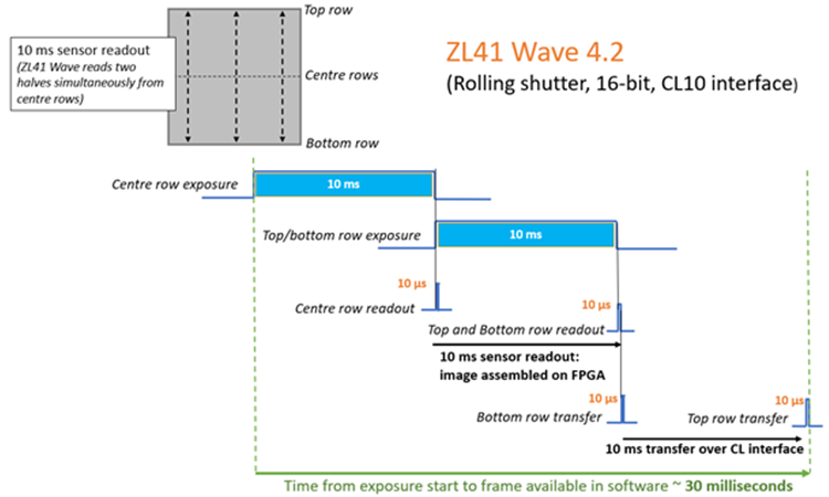
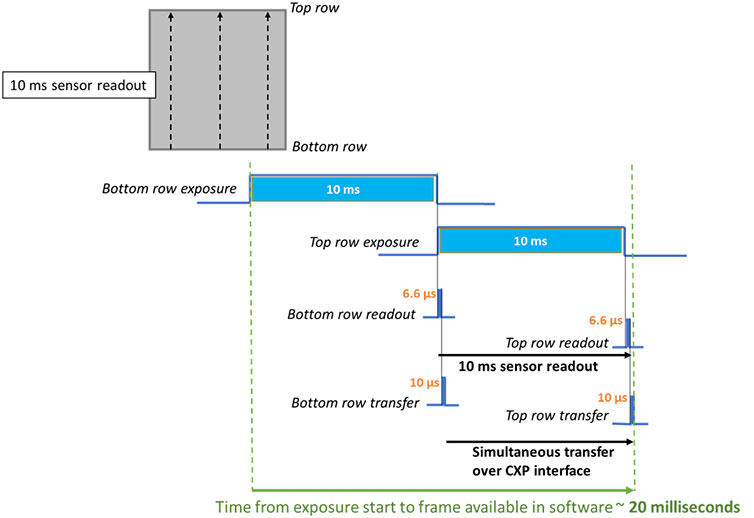
A key consideration for the usage of scientific imaging cameras as wavefront sensors is ‘latency’. Since wavefront sensors are part of a closed loop system in AO configurations, it is imperative that the image is quickly made available in software for real time processing, such that it can continually inform the deformable mirror system on how to reshape and flatten the incident wavefront on its way to the primary science detector.
This means that when comparing multiple cameras for potential wavefront sensing, we need to develop a clear understanding of the relative timings related to exposure, sensor readout and any image transfer overheads.
There can be some subjective variation around the definition of ‘latency’ within the timing flow of the imaging process. For the sake of standardising within the current comparative study, we will consider the total end-to-end time between the start of an exposure and the point at which the full image/ROI from that exposure is available for processing by software. We will also standardise by assuming an exposure time of 10 milliseconds (yielding 100 fps). Note however, that this 10 ms exposure corresponds to different ROI array sizes, and corresponding fields of view, across the three camera models that are being considered.
Figures 1 and 2 below show timing schematics comparing Marana 4.2B-6 to ZL41 Wave 4.2. The key latency distinctions between the considered sCMOS camera formats is as follows:
As such, the latency of Marana and Balor is reduced relative to that inherent to the ZL41 Wave platform. However, bear in mind that, as shown in section 1, faster sensor frame rates are possible for ZL41 Wave 4.2 relative to Marana 4.2B-6. In selecting the most appropriate wavefront sensor for your set-up, both factors should be considered within the context of your exact experimental requirements.
Key Imaging Parameters for Figures 1 and 2 (where options available):

Figure 1 – ZL41 Wave 4.2: Timings schematic representing exposure, readout and image transfer (over CameraLink interface).

Figure 2 – Marana 4.2B-6: Timings schematic representing exposure, readout and simultaneous image transfer (over CoaXpress interface). Note, Balor is very similar.
