Resources
 Part of the Oxford Instruments Group
Expand
Collapse
Part of the Oxford Instruments Group
Solution Note
Author: Tom Seccull, François Yaya, Jean-Luc Gach, Philippe Feautrier
Published: 01 Dec 2025 · Last updated: 09 Dec 2025
This article presents Andor CB2, a new camera platform improving upon the successful C-BLUE One family of high-speed CMOS cameras developed by First Light Imaging. Like C-BLUE One before it, CB2 is aimed at laser guided wavefront sensing for adaptive optics (AO) systems deployed at large (6-10 m) and extremely large (10+ m) ground-based optical/infrared observatories. CB2 carries forward many strengths from C-BLUE One, including high sensitivity and very low read noise at high frame rates. Likewise, CB2’s global shuttering and GigE data interface will continue to support synchronised wavefront sensing across the complex wide-field and multi-conjugate AO systems needed to maximise the performance of extremely large telescopes. The performance and main features of CB2 are presented and compared to those of C-BLUE One. CB2’s integrated liquid cooling (as opposed to C-BLUE One’s external cooling plate) supports deeper vibration-free sensor cooling and improved dark current suppression. CB2 will also support an optional wavefront sensing configuration which minimises both the distance and amount of optical material between a Shack-Hartmann lenslet array and the active silicon of the sensor.
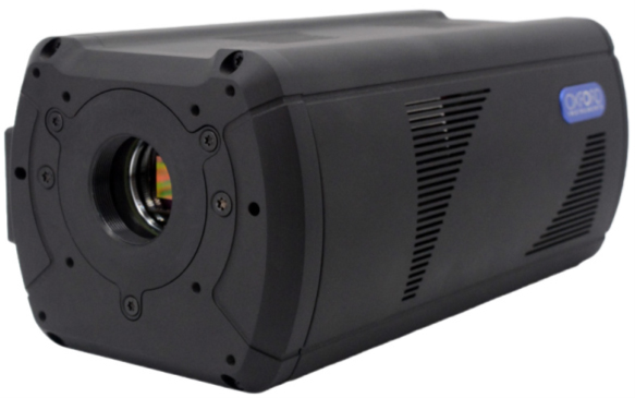
Figure 1. Andor CB2
Andor CB2 is a camera platform that supports a range of Sony IMX CMOS sensors applicable to both natural and laser guide star wavefront sensing: IMX426, IMX425, IMX420, IMX530, and IMX487. Table 1 provides an overview of the format, pixel pitch, read noise, and on-chip binning capability of these sensors. Figures 2 & 3 present their quantum efficiency curves. CB2’s capabilities are split broadly between three models. CB2 high-speed supports all the front-illuminated sensors that originally were part of the C-BLUE One (marked in orange in Table 1). CB2 high-res includes the wide-field high-resolution back-illuminated IMX530 sensor. CB2 high-res is a versatile camera capable of both high-performance wavefront sensing and scientific imaging. CB2 UV includes the ultraviolet (UV) sensitive IMX487 sensor, supporting both UV wavefront sensing and UV imaging.
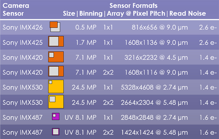
Table 1 - The formats of each of CB2's sensors. 2x2 on-chip binned formats are shown for the IMX420, IMX530, and IMX487 sensors. Sensor diagrams display all sensors at the same relative scale in colour with the size of their pixels displayed in grey, magnified 1000x.
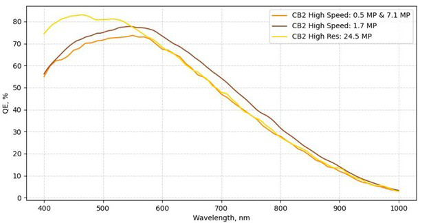
Figure 2 - QE curves for CB2's IMX426 (0.5 MP), IMX425 (1.7 MP), IMX420 (7.1 MP), and IMX530 (24.5 MP) sensors.
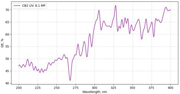
Figure 3 - QE curve for CB2's UV sensitive IMX487 sensor.
CB2 can drive all its sensors at the frame rates required for high performance wavefront sensing while maintaining minimal read noise. The three largest format sensors (IMX420, IMX530, IMX487) can perform on-chip 2x2 binning, providing flexible selection of the camera’s resolution and the opportunity to boost delivered signal-to-noise ratio (SNR) without the quadratic increase in read noise incurred by binning the data after readout. With a wide range of potential pixel pitches, CB2 can readily be coupled to a wide range of wavefront sensing optics. The extremely small 2.74 µm pixels offered with the CB2 high-res (IMX530 sensor) ensure that the camera has the resolution required for accurate Shack-Hartmann (SH) wavefront sensing with an off-axis laser guide star (LGS; where SH spots are pill-shaped rather than circular). Not only is this feature useful for LGS wavefront sensing at extremely large telescopes, but it also facilitates LGS wavefront sensing at any observatory that cannot launch an on-axis laser (i.e. the laser launch telescope is separated from the observing telescope).
Histograms showing the typical read noise distribution for each sensor are provided in Appendix A at the end of this article. The peak frame rates achievable for each sensor are plotted as a function of bit depth and the number of lines being read out in Appendix B.
CB2’s design improves on that of C-BLUE One by integrating liquid cooling of the sensor into the main camera body (an external cooling plate is no-longer needed). The dark currents of the sensors in CB2 are already very small, but with integrated liquid cooling CB2 supports improved vibration-free dark current suppression. Figure 4 compares the dark current performance for sensors in C-BLUE One to the same sensors in CB2. The integrated water cooling taps on CB2 are visible in Figure 5.
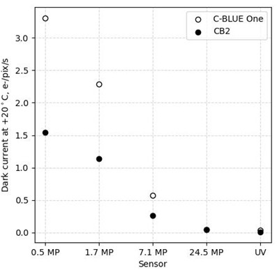
Figure 4 - Improvement of dark current for each sensor from C-BLUE One to CB2. C-BLUE One values are approximated by scaling values measured at +10°C by 2^(ΔT/8) where ΔT = +10°C. CB2 values are measured at +20°C.
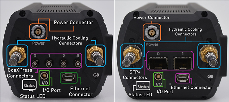
Figure 5 - The two interface configurations for CB2. The connectors for CB2's integrated liquid cooling are also visible. CB2 provides data ports compatible with either CoaXPress 2.0 (left; 12.5 Gb/s per cable) or GigE Vision (right; 10 Gb/s per outlet).
Each CB2 camera can support one of two data interfaces, CoaXPress 2.0 or 10 Gb ethernet via GigE Vision. CoaXPress supports stable high volume data transfer at rates of up to 12.5 Gb/s per cable. GigE is offered to support high speed data transfer over very long distances. At time of writing, use of only one 10Gb ethernet port is supported. CB2’s sensors will support dual port GigE data output in future, however. Once available, this capability will be activated by a simple firmware update.
CB2’s wavefront sensing (WFS) variant offers greater access to the camera’s sensor, allowing installation of a Shack-Hartmann lenslet array (or other optics) extremely close to the focal plane. Through special request, CB2 WFS can be provided without a sensor window, shrinking the separation between sensor and optic further. CB2 WFS supports higher sensitivity in wavefront sensing by minimising optical material between the wavefront sensor and the camera’s chip. This reduces both attenuation of signal and internal reflections that might produce ghost images and an increase in background photons.
A collection of histograms of the read noise distributions for different sensors in CB2.
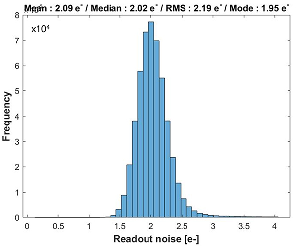
Figure A1 - Typical read noise distribution for CB2’s 0.5 MP (IMX426) sensor.
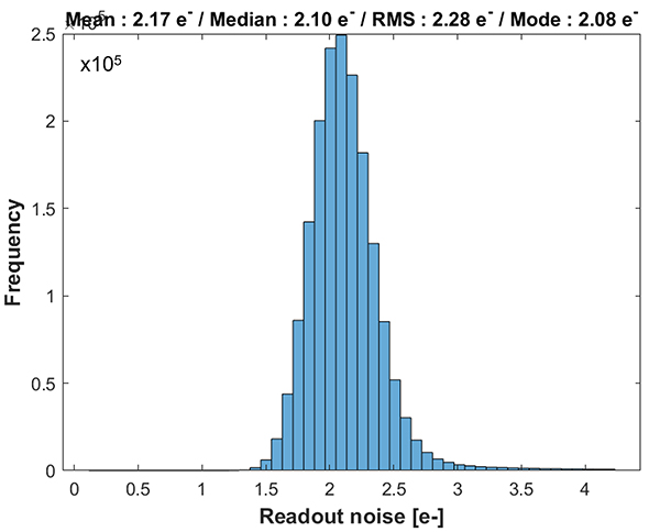
Figure A2 - Typical read noise distribution for CB2’s 1.7 MP (IMX425) sensor.
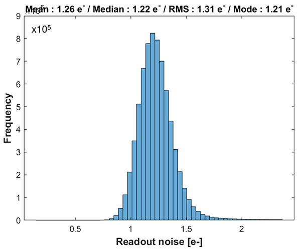
Figure A3 - Typical read noise distribution for CB2’s 7.1 MP (IMX420) sensor when unbinned.
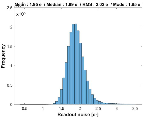
Figure A4 - Typical read noise distribution for CB2’s 7.1 MP (IMX420) sensor when binned 2x2.
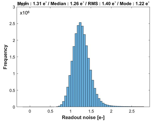
Figure A5 - Typical read noise distribution for CB2’s 24.5 MP (IMX530) sensor when unbinned.
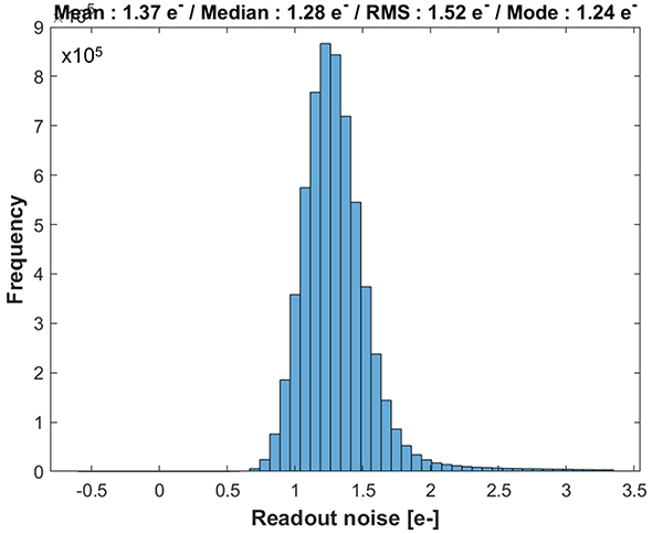
Figure A6 - Typical read noise distribution for CB2’s 24.5 MP (IMX530) sensor when binned 2x2.
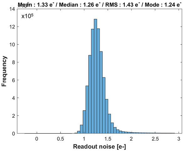
Figure A7 - Typical read noise distribution for CB2’s UV (IMX487) sensor when unbinned.
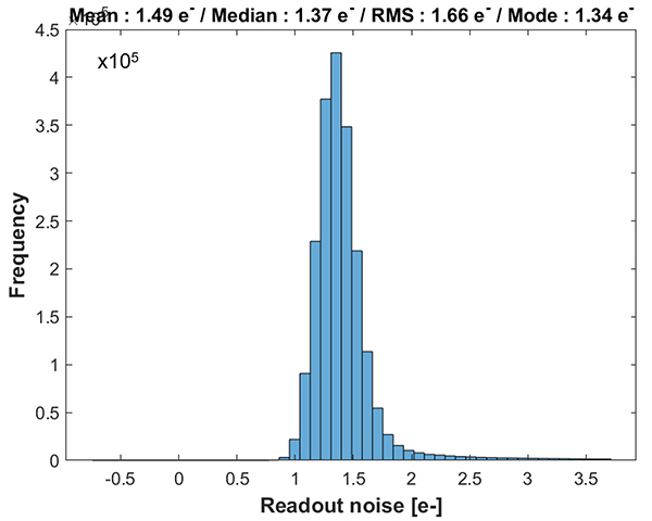
Figure A8 - Typical read noise distribution for CB2’s UV (IMX487) sensor when binned 2x2.
Peak frame rates for each of CB2’s sensors when operated with a range of bit depths and regions of interest (RoIs). Reading a smaller RoI and using a lower bit depth reduces the data volume of each image, allowing for faster readout and higher frame rates.
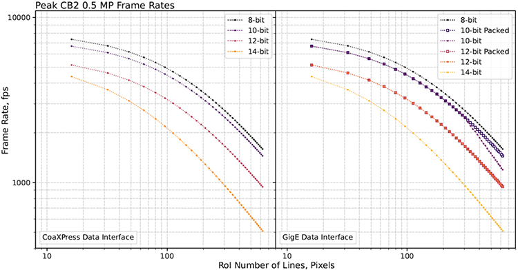
Figure B1 – Peak frame rates for CB2’s 0.5 MP (IMX426) sensor as a function of the number of lines read per image. Read out through CoaXPress is shown on the left and readout through GigE is shown on the right. Curves with different colours represent operation with different bit depths.
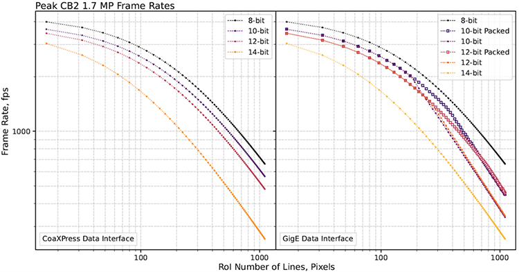
Figure B2 – Same as B1, but for CB2’s 1.7 MP (IMX425) sensor.
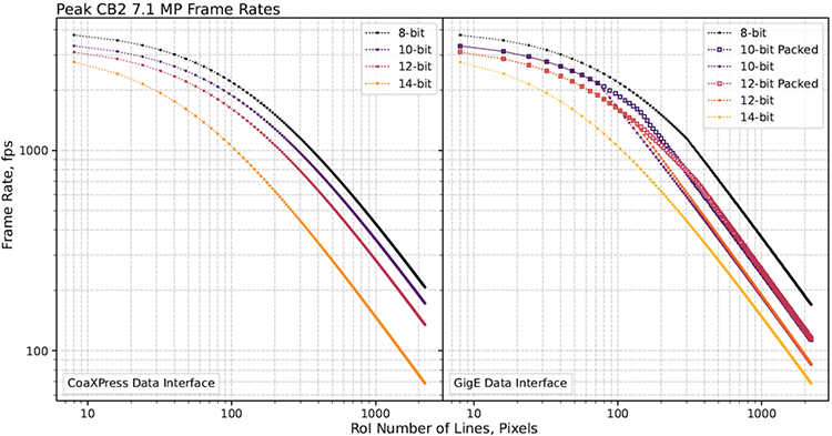
Figure B3 – Same as B1, but for CB2’s unbinned 7.1 MP (IMX530) sensor.
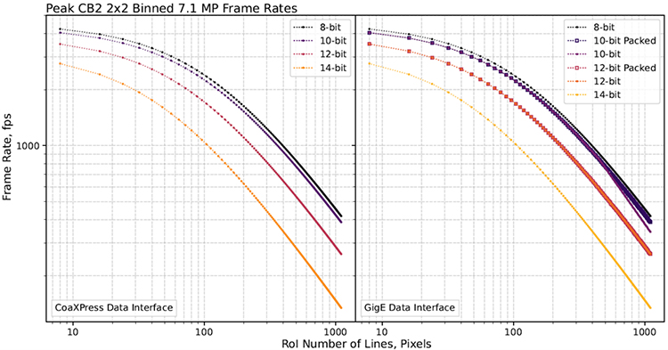
Figure B4 – Same as B1, but for CB2’s 7.1 MP (IMX530) sensor when binned 2x2 on-chip.
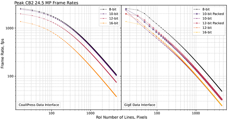
Figure B5 – Same as B1, but for CB2’s unbinned 24.5 MP (IMX530) sensor.
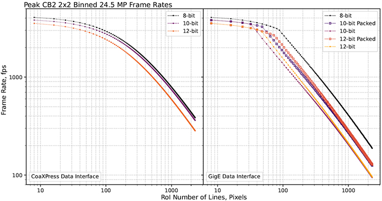
Figure B6 – Same as B1, but for CB2’s 24.5 MP (IMX530) sensor when binned 2x2 on-chip.
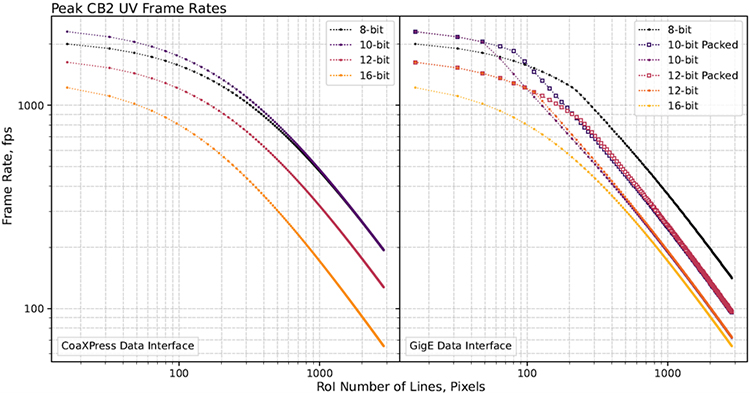
Figure B7 – Same as B1, but for CB2’s unbinned UV (IMX487) sensor.
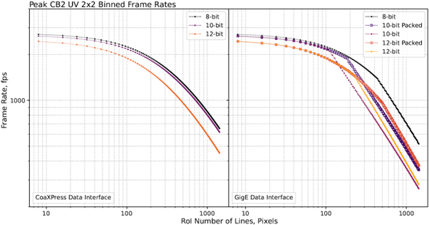
Figure B8 – Same as B1, but for CB2’s UV (IMX487) sensor when binned 2x2 on-chip.

© Oxford Instruments 2026
