Relative Orientation of Atomically Thin 2D Semiconductors
Author: C. Ruppert, M. Betz
Published: 01 Jan 2021 · Last updated: 24 May 2023
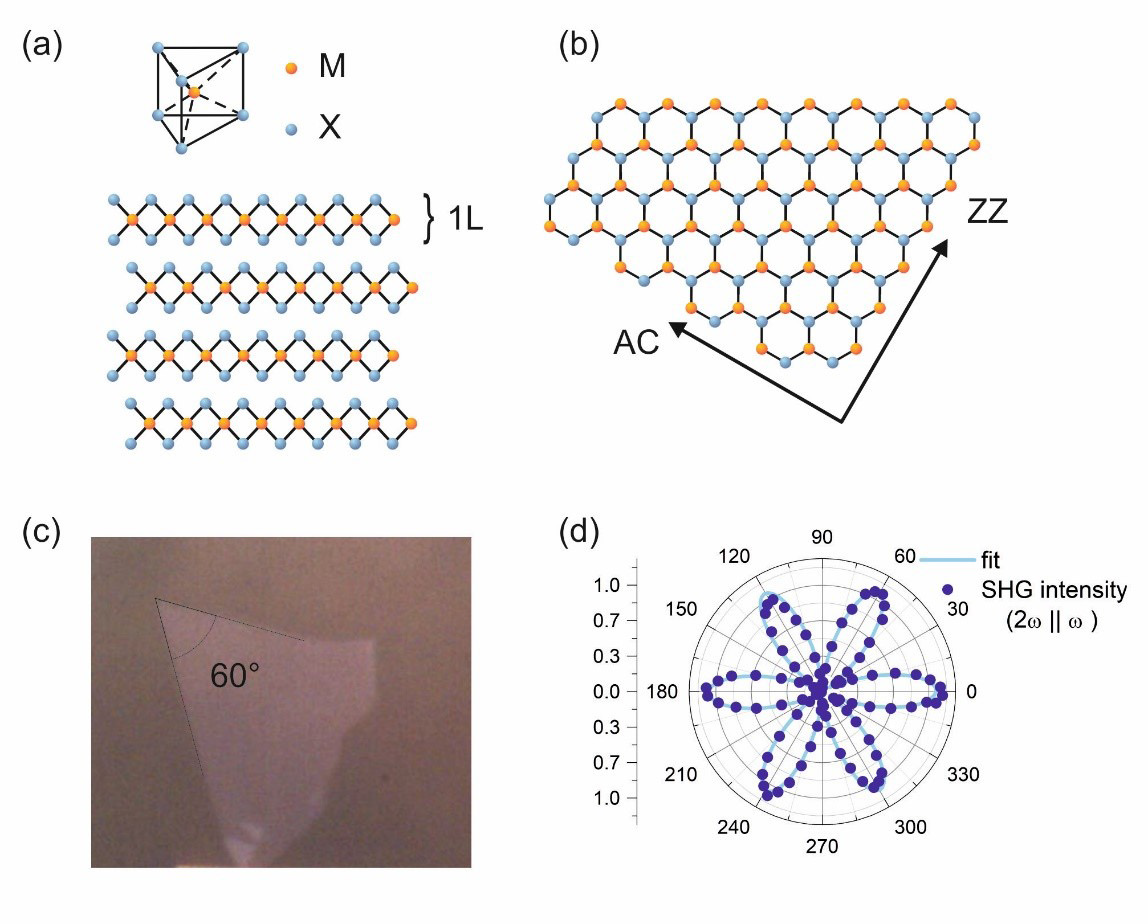
Atomically thin quasi two-dimensional materials have been studied very intensely in the past decade. Bulk crystals with a layered structure where strongly bound atomic sheets are held together by weak van der Waals’ forces can be cleaved down to single layers by mechanical exfoliation. Among them, transition metal dichalcogenides (TMDs) with the chemical formula MX2 consist of transition metal M of group IV, V or VI (e.g. Ti, V, Mo) and chalcogenide atoms X (S, Se, Te), see Fig 1 (a). Monolayers (1L) of these materials exhibit very unique fundamental properties which strongly differ from the corresponding bulk or multilayer form and research has extended towards their use in functional devices. Controlled stacking of single layers of the same or different material allows for, for example, manipulation of the optical and electrical properties. However, stacking two monolayers with precise alignment of the crystallographic axes requires a method to measure their relative orientation. Optical inspection of the exfoliated monolayers is not sufficient. Even though the crystals break favorably along specific crystal axes, armchair or zigzag, as depicted in Fig. 1 (b), an optical image does not allow to distinguish between them.
Figure 1: (a) Crystal structure of MX2 based transition metal dichalcogenides, (b) Monolayer crystal form the top with armchair (AC) and zigzag (ZZ) directions, (c) optical image of a monolayer crystal with sharp edges. The angle of 60° indicates that both edges are either AC or ZZ. (d) Polarization resolved SHG.
TMD monolayer crystal lattices in the 2H phase belong to the trigonal prismatic (D3h) point group. Due to the symmetry and enhanced by band structure, second harmonic generation (SHG) is strong. Exciting the TMD monolayer with linear polarized light under normal incidence and then filtering the SHG response with a linear polarizer, oriented along the fundamental polarization angle φ, results in a six-fold SHG intensity pattern I(2) II∝cos(3φ−3δ) 2, where the angle δ is the rotation of the armchair direction of the crystal relative to the x-axis, see Fig 1 (d). The maxima of the polarization-resolved SHG response coincide with the armchair directions of the TMD lattice. This allows for the determination of the lattice orientation of TMD crystals.
Experimental setup and results
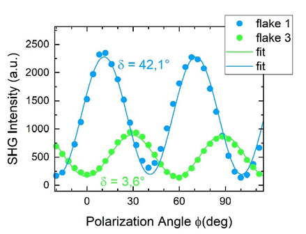
Monolayers of WS2 are mechanically exfoliated on PDMS and transferred onto fused silica substrates. To measure the relative orientation of the monolayers we use a Ti:Sapphire laser at 800 nm delivering short pulses of ~ 40 fs duration. A 100x 0.9 NA microscope objective is used to excite the sample and collect the back reflected fundamental and second harmonic light. A half wave plate rotates the polarization of the fundamental and the reflected second harmonic light is dispersed in a spectrograph (KYMERA-328i-B1-SIL) by a 300 l/mm grating and detected by a CCD (iDus DU416A-LDC-DD) cooled to -60 °C. The fundamental light is filtered out in front of the spectrograph. A polarizer filters the intensity of the component of the second harmonic parallel to the fundamental light. With careful considerations to account and compensate for the different reflectivities for s- and p-polarized light from the sample to the detector, the measured SHG intensity component parallel to the fundamental field for various orientations of the fundamental with respect to the sample will look like the data shown in Fig. 1 (d). Figure 2 shows the polarization resolved SHG after transfer of two monolayers onto the same fused silica substrate. A fit with the function mentioned above reveals the relative angle between the crystals to be about 40°.
Figure 2: Polarization resolved SHG for two different monolayers.
References
(1) Butler, S. Z.; Hollen, S. M.; Cao, L.; Cui, Y.; Gupta, J. A.; Gutiérrez, H. R.; Heinz, T. F.; Hong, S. S.; Huang, J.; Ismach, A. F.; Johnston-Halperin, E.; Kuno, M.; Plashnitsa, V. V.; Robinson, R. D.; Ruoff, R. S.; Salahuddin, S.; Shan, J.; Shi, L.; Spencer, M. G.; Terrones, M.; Windl, W.; Goldberger, J. E. ACS Nano 2013, 7 (4), 2898–2926.