Resources
 Part of the Oxford Instruments Group
Expand
Collapse
 Part of the Oxford Instruments Group
An important parameter that is often used to evaluate the sensitivity of a camera is the signal to noise ratio. This can be used to determine how different cameras may perform at light regimes that simulate those of a given research conditions. In this article we will look at the theoretical prediction of signal to noise for a typical CCD or sCMOS camera by looking at both signal and noise elements.
If we assume we have a number of photons P falling on a camera pixel with a Quantum Efficiency DQE this will generate a signal of Ne electrons as below

The incoming photons have an inherent noise variation or uncertainty to the signal itself. This is known as photon “Shot” noise. As the photons follow Poisson statistics the signal noise, may be described as:

The internal processes of the camera generate noise. Some of these are largely set by the sensor design itself, but also how the sensor has been implemented and packaged into the camera design will influence these.
These noise sources are:

readout which is the noise generated from the sensor readout process.
dark is the noise resulting from thermally generated electrons (often called dark signal as it is produced in the absence of light. Dark current can be reduced by cooling the sensor – click here to read about the effect of cooling on dark current in sCMOS cameras.

For EMCCD cameras there is an additional noise factor that is called “EM noise” or “Excess Noise Factor”. This is a result of the EM gain amplification and effectively increases the shot noise by a factor of 1.41. Note that this is not an additional noise, but an increase in the variability of the signal. When EMCCD cameras are considered this additional noise factor must be considered.
For sCMOS cameras, each pixel effectively has its own amplifier. An effect of this is that the some pixels will have a higher or lower read noise value. The read noise of sCMOS cameras has an asymmetric distribution that can be described as either a median and/or a rms value. Although the median value is often specified for sCMOS cameras, when considering signal to noise ratios it is the rms value that is used.
Another noise consideration for sCMOS sensor architectures is fixed pattern noise. Due to the very slight differences of each pixel they will in turn have very slight differences in their response to light. A correctly optimised camera uses “pixel maps” to account for these differences so that fixed pattern noise is not generally an issue. Fixed pattern noise is not a factor in signal to noise calculations so is covered in more detail in other articles.
We can put the signal and noise components together and generate an expression for the signal to noise ratio for a typical CCD or sCMOS camera:

Substituting for the expressions for Noise we can see the equation for signal to noise for a camera is as follows:

The thermal noise component Ndark is a function of temperature and exposure time.
The signal to noise ratio curves may be plotted on a per pixel basis or a per unit area basis. Different camera sensors will have different pixel sizes and sensor sizes so it is important to consider these parameters if comparisons between different sensors are being made.
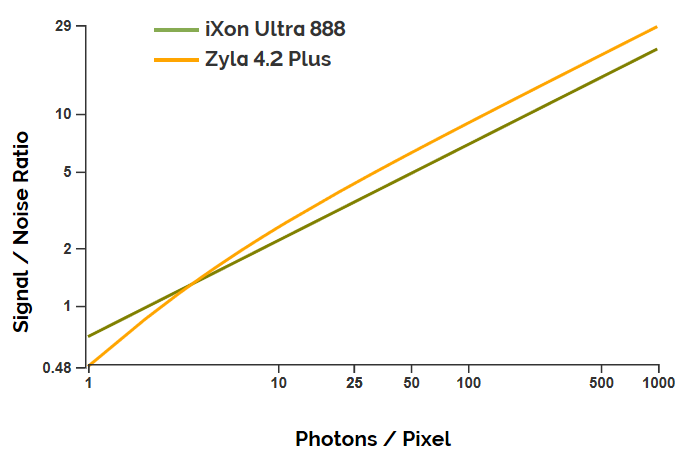
The Andor Signal to Noise Calculator can be used to make useful comparisons between cameras or for different settings such as exposure time. An example plot for the signal to noise ratio for a Zyla 4.2 Plus sCMOS camera versus an iXon Ultra 888 EMCCD camera is shown in figure 1 (expressed per pixel).

There are several points that we can take away from this example:
SNR can be a useful tool to help compare the sensitivity of different cameras, or look at the impact of adjusting camera settings. Ultimately these theoretical comparisons should be followed up with camera demos to confirm performance is suitable for the unique parameters of any given experimental set-up.
Date: September 2019
Author: Dr Alan Mullan
Category: Technical Article
