Resources
 Part of the Oxford Instruments Group
Expand
Collapse
Part of the Oxford Instruments Group
Application Notes
Author: Andor
Published: 10 Feb 2021 · Last updated: 10 Feb 2021
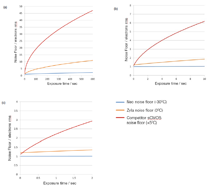
Figure 1 - Plots of sCMOS noise floor (read noise and dark noise combined in quadrature) versus exposure time, at sensor cooling temperatures of +5°C measured from competitor's sCMOS camera vs. 0°C and -30°C (measured from Zyla and Neo sCMOS respectively). Plots are shown over three ranges of exposure time: 0 - 2 sec, 0 - 10 sec and 0 - 600 sec.
Since the read noise of scientific CMOS technology is extremely low, very careful attention must be given to the contribution of thermal noise, which if left unchecked carries potential to sacrifice the low noise floor advantage of the technology. Deep thermoelectric cooling provides the key to maintaining a minimized detection limit through suppression of darkcurrent, whilst simultaneously reducing the occurrence of hot pixel blemishes.
Part 1 - Effect on Noise Floor
The ultra-low value of 1 electron rms read noise available from sCMOS cameras is entirely unprecedented, and dramatically outperforms even the best CCD to date. Read noise is an important contributor to the noise floor detection limit of a camera, but the noise associated with thermal signal, darkcurrent, should never be overlooked. In CMOS cameras especially, even modest exposure times can result in a significant increase in dark noise. Furthermore, since scientific CMOS cameras have a much lower read noise baseline, then the percentage increase in dark current can be proportionally larger.
Andor's sCMOS cameras have each been designed to implement effective sensor cooling. In fact, the Andor Neo sCMOS platform is unique in the market in that it is the only commercially available CMOS camera with vacuum technology, offering the level of deep thermoelectric cooling necessary to absolutely minimize the detrimental influence of dark noise. Figure 1 shows theoretical plots of noise floor versus exposure time, at three different cooling temperatures, +5°C, 0°C and -30°C. The parameters used in determining the overall noise floor are based on a typical read noise 'baseline' of ~ 1 electrons, combined with the measured typical darkcurrent of the CIS 2051 sCMOS sensor at each of the temperatures, the values for 0°C and -30°C from the Andor Zyla and Neo sCMOS cameras respectively. The darkcurrent value used for +5 C has been taken from the spec sheet of a competitive camera using the same sensor. Combined noise is calculated in quadrature, i.e. using the 'square root of the sum of the squares method'.
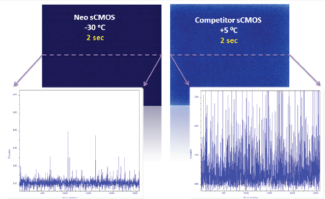
Figure 2 - Thermal noise can sacrifice the sCMOS low detection limit. Low light images recorded with a Neo sCMOS at -30°C versus a competing sCMOS @ +5°C, Shown with same relative intensity scaling; 2 sec exposure time; 560MHz readout speed. Comparative line intensity profiles from a single row is also shown for each case.
Even within the exposure range up to 2 sec, the low noise floor can be notably sacrificed by almost 200% at the higher temperature of +5°C. Cooling to -30°C maintains the 1 electron noise floor over this short exposure range. At an exposure time of 10 sec, the noise floor associated with +5°C is significantly compromised to a value greater than 6 electrons, i.e. x6 greater than the read noise, whereas the noise is maintained to values less than 1.5 electrons with deeper cooling.
For very low light measurements, such as in chemiluminescence detection, it can sometimes be desirable to apply exposure times up to or greater than 10 minutes. At 600 sec, unless deep cooling is applied, the thermal contribution to the noise floor would become excessively large, shown in graph C as reaching > 45 electrons at +5°C. Holding the cooling temperature at -30°C would result in the noise floor being held at a more modest 2.4 electrons over this extensive exposure period.
Figure 2 shows dark images of 2 second exposure, taken with Neo sCMOS versus that of a competitor's sCMOS (same sensor type) @ + 5°C. The same relative intensity scaling (in terms of absolute electrons) is used to display each. The detrimental effect of elevated bulk darkcurrent is evident, manifest also in the comparative single row intensity profiles derived from each image.
Part 2 - Effect on Hot Pixel Blemishes
CMOS sensors are particularly susceptible to hot pixel blemishes. These are spurious noise pixels that have significantly higher darkcurrent than the average. Through deep TE cooling of the sensor, it is possible to dramatically minimize the occurrence of such hot pixels within the sensor, meaning that these pixels can still be used for useful quantitative imaging. Table 1 shows that the typical number of pixels with higher than average darkcurrent can be dramatically limited in practice through cooling of the sensor, meaning that they are not required to be treated by interpolation filters. Such interpolation over pixel blemishes can be detrimental in some applications that depend on total quantitative integrity over a limited set of pixels, for example in localization based super-resolution microscopy (such as PALM and STORM techniques).
| Cooling Temperature | # hot pixels with > 2e-/pix/sec |
| +5°C | 28,500 |
| -30°C | 1,800 |
Table 1 - Typical number of hot pixels (i.e. higher than average darkcurrent pixels) of the 5.5MP 2051 sCMOS sensor that show darkcurrent greater than 2 e-/pix/sec at cooling temperatures of +5°C and -30°C.
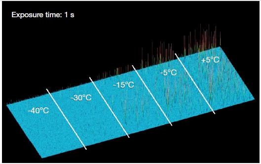
Figure 3 (a) - Blemishes at different temperatures for 1 sec exposure.
Figure 3 (a) shows a 3D intensity plot of the same region of a sCMOS CIS2051 sensor at a number of different cooling temperatures, each recorded with only 1 sec exposure time in rolling shutter mode. It is clear that cooling to -30°C and beyond is highly effective in reducing the occurrence of hot pixel spikes, thus offering both an aesthetically cleaner image and a greater proportion of useable and meaningful pixels. This in turn means that significantly fewer pixels need be treated using a nearest neighbor median replacement algorithm. Even using very short exposure conditions of 30 ms, there are still significant numbers of hot pixels present at higher cooling temperatures, as illustrated in figure 3 (b).
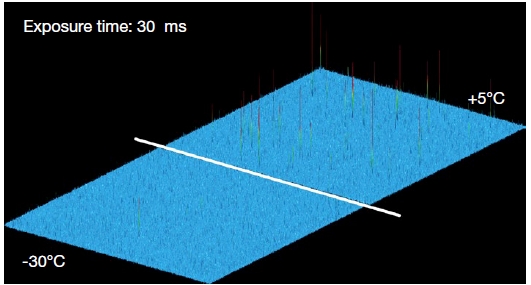
Figure 3 (b) - Blemishes at -30°C vs +5°C for 30 ms exposure
Part 3 - Minimization of Vibration
Many optical configurations are sensitive to vibrations from the camera fan, such as patch clamp or combined optical/AFM set-ups. The deep cooling advantage of Neo means that the internal fan can be turned off by instead opting to flow water through the conveniently located connections. Andor's Neo offers:
'Liquid cooling' through the camera allows minimization of vibration while still stabilizing at -40°C. Alternatively, if complete vibration free operation is required without water cooling, the Neo fan can turned off for a limited period of time, during which the camera is passively cooled. Table 2 shows typical fan-off durations that apply when the Neo camera is operated in a + 25°C ambient environment.
Table 2 - Examples of what fan-off durations achievable across a range of cooling temperatures and readout speeds when operating Neo sCMOS in an ambient environment of 25°C
| Sensor Readout Speed | Selected Sensor Temperature | Duration Before Fan Is Forced On |
| 560 MHz | 0°C | 60 minutes |
| 560 MHz | 5°C | 79 minutes |
| 560 MHz | 15°C | 93 minutes |
| 560 MHz | -15°C | 9 minutes |
| 560 MHz | -30°C | 5 minutes |
| 200 MHz | -15°C | 18 minutes |
| 200 MHz | -30°C | 12 minutes |

© Oxford Instruments 2026
