Resources
 Part of the Oxford Instruments Group
Expand
Collapse
Part of the Oxford Instruments Group
Application Notes
Author: Andor
Published: 10 Feb 2021 · Last updated: 15 Jul 2025
The technique of PLD (Pulsed Laser Deposition) has been used to deposit high quality films of materials for more than a decade. The technique uses high power laser pulses (typically ~108 Wcm-2) to melt, evaporate and ionize material from the surface of a target. This "ablation" event produces a transient, highly luminous plasma plume that expands rapidly away from the target surface. The ablated material is collected on an appropriately placed substrate upon which it condenses and the thin film grows. Applications of the technique range from the production of superconducting and insulating circuit components to improved wear and biocompatibility for medical applications. In spite of this widespread usage, the fundamental processes occurring during the transfer of material from target to substrate are not fully understood and are consequently the focus of much research.
In principle PLD is an extremely simple technique, which uses pulses of laser energy to remove material from the surface of a target, as shown schematically on the right.
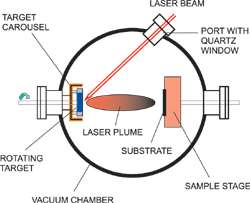
PLD schematic
The vaporized material, containing neutrals, ions, electrons etc., is known as a laser-produced plasma plume and expands rapidly away from the target surface (velocities typically ~106 cm.s-1 in vacuum). Film growth occurs on a substrate upon which some of the plume material recondenses. In practice, however, the situation is not so simple, with a large number of variables affecting the properties of the film, such as laser fluence, background gas pressure and substrate temperature. These variables allow the film properties to be manipulated somewhat, to suit individual applications. However, optimization can require a considerable amount of time and effort. Indeed, much of the early research into PLD concentrated on the empirical optimization of deposition conditions for individual materials and applications, without attempting to understand the processes occurring as the material is transported from target to substrate.
The technique of PLD was found to have significant benefits over other film deposition methods, including:
1. The capability for stoichiometric transfer of material from target to substrate, i.e. the exact chemical composition of a complex material such as YBCO, can be reproduced in the deposited film.
2. Relatively high deposition rates, typically ~100s Å/min, can be achieved at moderate laser fluences, with film thickness controlled in real time by simply turning the laser on and off.
3. The fact that a laser is used as an external energy source results in an extremely clean process without filaments.Thus deposition can occur in both inert and reactive background gases.
4. The use of a carousel, housing a number of target materials, enables multilayer films to be deposited without the need to break vacuum when changing between materials.
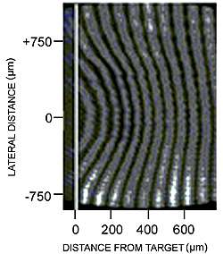
Interferogram of a Magnesium plasma plume expanding into vacuum taken 46nS after the ablation pulse struck the target surface. Laser fluence (2.0 ±0.2) JCM -2 on target, 2nS ICCD gate width. Image courtesy of Physics Department, Queen's University, Belfast.
In spite of these significant advantages, industrial uptake of PLD has been slow and to date most applications have been confined to the research environment. There are basically three main reasons for this:
1. The plasma plume created during the laser ablation process is highly forward directed, therefore the thickness of material collected on a substrate is highly non-uniform and the composition can vary across the film. The area of deposited material is also quite small, typically ~1cm2, in comparison to that required for many industrial applications which require area coverage of ~(7.5 x 7.5) cm.
2. The ablated material contains macroscopic globules of molten material, up to ~10μm diameter. The arrival of these particulates at the substrate is obviously detrimental to the properties of the film being deposited.
3. The fundamental processes, occurring within the laser-produced plasmas, are not fully understood; thus deposition of novel materials usually involves a period of empirical optimization of deposition parameters.
To a large extent the first two problems have been solved. Films of uniform thickness and composition can be produced by rastering the laser spot across the target surface and / or moving the substrate during deposition. Line-focus laser spots have also been used to obtain large area coverage. The particulate material was initially removed from the plume using a mechanical velocity filter, although recently more elaborate techniques, involving collisions between two plasma plumes or off-axis deposition, have been used to successfully grow particulate-free films. The third problem will be resolved by the development of computer simulations to describe PLD, and will further our understanding of the fundamental physics and chemistry involved in the deposition process. However, a large amount of experimental data, obtained under accurately controlled and defined conditions, is required to assist the verification of such models.
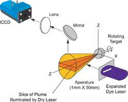
Typical system configuration for LIF data acquisition
The PLD process can be crudely split into two sections, i.e. the plasma creation and expansion, followed by film growth at the substrate. In the current article only data relating to the initial stage will be presented. The temporal evolution of densities, temperatures and velocities within laser-produced plasmas can only be determined using fast diagnostics (~ns time-scales), due to the high luminosity and transient nature of the plumes.
A variety of techniques, including interferometry, optical spectroscopy and Laser-Induced Fluorescence (LIF), are used to investigate different stages of the plasma creation and expansion. At short delay times after the ablation pulse (<100ns) Mach-Zehnder interferometry has been used to study the free electron component within the plume expanding into vacuum. The time-varying electron density was calculated from a series of interferograms of the plume, captured using an Andor ICCD camera with a 2ns gate width. A typical image is shown in the on the left.
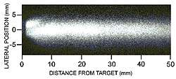
LIF image of ground state, singly ionized Titanium species expanding along the target normal into vacuum. The image was recorded 3μS after the ablation pulse struck the target surfaceand ata laserfluence of (5.1 ±0.2) JCM-2. Image courtesy of Physics Department, Queen's University, Belfast.
The plume emits high intensity broadband emission during the initial stages of the expansion, which could easily saturate the detector. However, the short gate width of the ICCD blocks out the majority of this continuum emission, enabling the interferogram to be "extracted" from the larger background signal. These "snapshots" show measurable electron densities extending out to ≤1mm from target at these delays with peak densities >1017cm-3, calculated using an Abel inversion technique. At longer delays (and under similar conditions) LIF was used to map the neutral and ionic components within slices of the plume. A typical experimental configuration used to obtain LIF measurements is illustrated on the right.
The picture on the left shows a LIF image of ground state Ti II ions within a plume, recorded with a 5ns ICCD gate width.
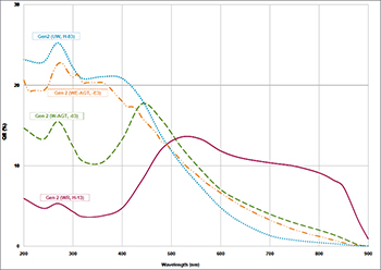
Gen 2 photocathode QE curves relevant to Pulsed Laser Deposition
Once again the short gate width is required to extract the relatively weak LIF signal from the more intense plasma self-emission. The signal was observed to extend beyond 50mm at 3μs delay, with peak densities ~1010cm-3 (obtained using a combination of LIF and absorption spectroscopy data). Data from these diagnostics were used to construct an overall picture of the plume expansion for comparison with models of the laser ablation process. These two examples show both the species density and spatial extent of the plume varying over several orders of magnitude during a timescale of less than a few microseconds, illustrating the flexibility required from both the diagnostics and detectors used in such experimental investigations.
As our understanding of the plasma processes increases, these investigations and computer models may be applied to more complex systems than those considered in the present case and will include the deposition stage of the process. Eventually it is hoped that the computer simulations can be used for predictive purposes when novel materials are to be deposited using PLD. Fast ICCD's will continue to be the detector of choice for acquiring the data necessary to develop these computer models, with their role perhaps changing to in-situ monitors for process control, once PLD becomes commercially viable for industrial applications.
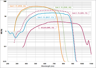
Gen 3 photocathode QE curves relevant to Pulsed Laser Deposition

© Oxford Instruments 2026
