Resources
 Part of the Oxford Instruments Group
Expand
Collapse
 Part of the Oxford Instruments Group
Calculating dynamic range in EMCCDs has often been a source of confusion, due to the additional requirement to factor in EM gain and the extended well capacity of the gain register. High dynamic range can be accessed in EMCCDs with careful fine tuning of EM gain.
Calculating Dynamic Range in an EMCCD camera is a slightly more complicated story than for conventional CCDs. This is because of the favourable effect of EM gain on the detection limit vs. the limiting effect of EM gain on the full well capacity. The easiest way to address this is to first take each parameter separately:
The main function of EMCCD is to eliminate the read noise detection limit and enable detection of weak photon signals that would otherwise be lost within this noise floor. With EM gain, the detection limit is given by the 'Effective Read Noise', i.e. the read noise divided by the gain multiplication, down to one electron. Why never less than one? This stems from the definition of detection limit, which is essentially "the signal equal to the lowest noise level". Since you can't get a signal less than one photon, then the detection limit should never be taken as less than one electron.
For example, the iXon Ultra 888 has a read noise of ~45 electrons @10 MHz with EM gain off. At EM gain x2, the new detection limit can be considered to be 22.5 electrons effective read noise, at x5 it will be 9 electrons, at x45 it will be 1 electron. At x100, the Effective Read Noise will be 0.45 electrons, but as far as the dynamic range calculation is concerned, this detection limit must still be treated as 1 electron.
One might imagine that applying EM gain will decrease the full well pixel capacity proportionally. This is indeed the case, but a buffer has been built into EMCCD cameras to enable at least some EM gain to be applied while maintaining the original well capacity. This buffer is in the form of a higher capacity in the gain register pixels, where the multiplication actually takes place. So, the true capacity is given by the capacity of the pixels of the sensor, but as you apply EM gain this holds only up until the point where the larger capacity of the gain register pixels also become saturated by applied EM gain. After that point, you have to correct the 'effective' full well of the sensor to be equal to the full well of the gain register divided by the gain.
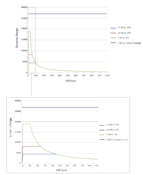
These above factors combined mean that as EM gain is increased, Dynamic Range will increase with gain to a maximum, level off and then reach a point at which it begins to deplete again with further gain.
iXon Ultra 888 back-illuminated EMCCD can be read out at either 30, 20, 10 or 1 MHz speeds. This offers extended flexibility to balance Dynamic Range vs. frame rates. Furthermore OptAcquire can be used to select optimal Dynamic Range settings at fastest and slowest speeds.
This can seem complicated, but fortunately these DR vs EM gain relationships can be readily plotted out and visualized in graphical form, as exemplified in Figure 1.

Figure 1 - Dynamic Range vs EMCCD gain, for iXon Ultra 897. Shown for EM amplifier @ 17, 10 and 1 MHz readout speed and for Conventional amplifier at 1 MHz readout speed. Well capacities used in DR calculation are characteristic of the CCD97 512 x 512 back-illuminated L3 sensor from E2V. Dynamic range only exceeds 14-bits max @ 1 MHz, through either amplifier.
There are a number of interesting points to note from these plots:
Note: There is a direct relationship between readout noise and maximum dynamic range at a given readout speed. Lower readout noise affords higher dynamic range. The readout noise specification used in calculating dynamic range must be with EM gain turned off, as quoted in all iXon spec sheets. We note, however, that another prominent EMCCD provider chooses to quote their lowest read noise value, not for EM gain-off, but only for EM gain x4, x6 or x10 (model dependent). In this case, to arrive at the real read noise spec you would have to multiply the quoted figure by x4, x6 or x10.
Date: N/A
Author: Andor
Category: Technical Article
