Resources
 Part of the Oxford Instruments Group
Expand
Collapse
Part of the Oxford Instruments Group
Application Notes
Author: Andor
Published: 10 Feb 2021 · Last updated: 30 Jul 2025
Please note, before reading this document it is highly advised to read the separate Andor technical note entitled: ‘Rolling and Global Shutter’
Rolling and true Global (Snapshot) Exposure

The sCMOS sensor integrated in both Neo 5.5 and Zyla 5.5 sCMOS cameras was designed with a ‘5T’ (5 transistor) pixel architecture that uniquely offers a choice of both Rolling and true Global Shutter modes (also called Rolling and Global Exposure modes). This provides superior application and synchronization flexibility and the ability, through global shutter, to closely emulate the familiar 'Snapshot' exposure mechanism of interline CCDs. The ‘4T’ sensor that is used in Zyla 4.2, while offering higher QE, is fundamentally a Rolling Shutter sensor.
While it is possible to simulate global shutter exposure using rolling shutter mode in combination with a strobed/pulsed light source, this is generally at the expense of increased dead time (i.e. the amount of time during the exposure cycle that photons are not being collected) and/or frame rate, as well as increased complexity. By contrast, true global exposure synchronization facilitates up to 0% dead time, faster frame rates and a much less complex experience of synchronization to peripheral switching devices, e.g. z-stage or wavelength switcher.
Please read the technical note entitled ‘Rolling and Global Shutter’ for more in-depth mechanistic description and comparison between these two exposure modes. In contrast, this synchronization-oriented technical note is aimed specifically as a guide to those wishing to optimally synchronize to sCMOS cameras, making use of either rolling or global shutter modes of Neo or Zyla sCMOS cameras.
TTL Fire camera outputs – Rolling Shutter
The timing diagram in Figure 1 illustrates the various TTL ‘Fire’ outputs that are available for use with Andor’s Zyla sCMOS camera. Such TTL outputs can be used to trigger pulsed (or strobed) light sources; however, not all of them are viable for practical use in this purpose. For example, if Fire 1 is used then the light source would be synchronized only to the exposure duration of ‘rows 1’ (i.e. the 2 rows at the center of the sensor) and these rows would receive 10 ms more exposure to light than the rows at the very top and bottom of the sensor (‘rows n’). Conversely, if Fire n is used, the top/bottom rows would receive 10ms more illumination than row 1. Note, if an ROI is used, this disparity would become less than 10ms, dependent on the ROI size and position relative to the horizontal centre axis.
The solution is to use either the Fire ‘ALL’ or Fire ‘ANY’ outputs. These can be used to trigger the light to turn on either during that part of the exposure sequence during which all rows of the same exposure are active to light (ALL), or during the entire exposure sequence (ANY). The former condition, ‘FIRE ALL’, describes the trigger output that is used in simulated global shutter synchronization mode to avoid the ‘transient’ phases of the exposure cycle, and associated common rolling shutter artifacts, during which rows are being activated to exposure or read out (described in more detail below).
Figure 2 shows a series of images acquired using the Zyla 5.5 sCMOS mounted on an imaging rig, imaging a hole pattern object with relatively uniform LED illumination. Different fire outputs from the camera are used to trigger.
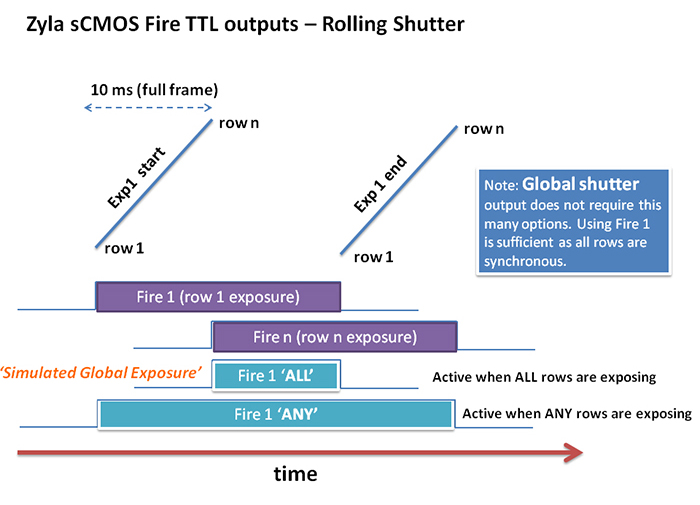
Figure 1 – Fire TTL outputs available from Zyla sCMOS camera in Rolling Shutter mode
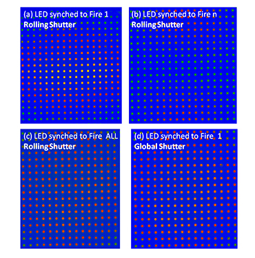
Figure 2 - Images acquired using the Zyla sCMOS imaging a hole pattern with relatively uniform LED illumination. Different fire outputs from the camera are used to trigger the LED light source, with even amounts of illumination occurring only from Fire ALL Rolling Shutter and from Global Shutter configurations.
The LED light source to come on. The exposure time input is long enough such that there is overlap between Fire 1 and Fire n (i.e. such that ‘FIRE ALL’ can be meaningfully used). The illumination gradients are clearly observable when Fire 1 or Fire n are used, whereas use of ‘FIRE ALL’ results in more even illumination (any residual gradient is purely optical). Using any Fire TTL output in true Global Shutter mode also results in even illumination of the array, in fact with greater signal intensity due to a 0% dead time of photon collection (i.e. photons are not wasted).
True Global Exposure versus Simulated Global Exposure Synchronization
Many applications require that photons are collected from the sample ONLY during a ‘non-transient’ period of the overall exposure cycle, in order to avoid the possibility of spatial distortion of moving objects. In rolling shutter mode, 10 ms is required to first activate all the rows of the full sensor array into an exposing state (progressing row by row from the centre outwards), and a further 10 ms is required at the end to readout the sensor. These are referred to in this document as the ‘transient periods’ of the exposure cycle.
By contrast, in true global shutter mode, there are no transient periods within the exposure cycle. At the start of the exposure, each pixel simultaneously begins to collect charge and is allowed to do so for the duration of the exposure time. At the end of exposure, each pixel transfers charge simultaneously to its readout node.
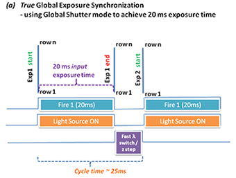
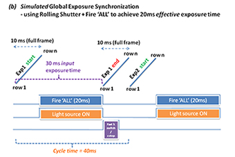
Figure 3 – Timing diagrams comparing methods of synchronizing using (a) True Global Shutter mode and (b) Simulated Global Exposure Synchronization which uses Rolling Shutter combined with Fire ALL output to activate light source.
In rolling shutter however, it is often required to use a triggering mechanism that ensures light is only collected from the sample during the non-transient part of the exposure cycle, which can be thought of as the effective exposure time. This mechanism makes use of a particular TTL Fire output from the camera (in Andor sCMOS cameras referred to as ‘FIRE ALL’) which is active only when all rows are exposing. This output can be used to inform a pulsed (strobe) light source to illuminate the sample during this non-transient period. This approach is referred to as simulated global exposure synchronisation.
The timing diagrams in Figure 3 illustrate the distinction between these two methods of synchronization, assuming that we wish to synchronize to a fast (5 ms) switching device and that we require 20 ms of effective exposure to illuminate each cycle. The vertical lines of the true global exposure start and end indicate that all pixels of the entire array are activated simultaneously, whereas the diagonal lines of Rolling Shutter indicate that it takes 10 ms to start and a further 10 ms to end the exposure (assuming full array).
In true Global Exposure Synchronization, any of the available Fire TTL outputs can be utilized since there is no timing difference between row 1 (centre) and row n (top & bottom rows of the array), but Fire 1 is illustrated as being used in this example. Significantly, it is possible to utilize the ‘overlap’ function, whereby the next exposure can begin immediately after the peripheral device has moved, the readout of the 1st exposure happening ‘behind the scenes’ from the readout nodes of each pixel. Thus, even though it still takes 10 ms for the full array to readout, the next exposure can start before readout is compete. This is an important distinction of a true global shutter mechanism, whereby the charge from all pixels are simultaneously transferred into the pixel readout nodes for readout to begin concurrently with onset of the subsequent exposure, during which all pixels are simultaneously activated to expose again. As such, faster cycle times and lower dead time can be achieved, in this example the cycle time being 25ms (i.e. the exposure time plus the peripheral device switching time), yielding 40 fps, with only 20% dead time. Furthermore, the faster the peripheral device is used, the shorter the cycle time that can be achieved.
In contrast, the simulated Global Exposure Synchronization mechanism uses rolling shutter and activates the light source using the ‘FIRE ALL’ TTL output. The sequence shown assumes ‘non-overlap’ of exposures, such that we can maintain separate control over the start and end of each individual exposure. Due to the 20 ms worth of transient exposure activation/readout time per cycle, the overall cycle time is extended to 40 ms, yielding 25 fps. Given that the light source is on for only 20ms, this represents a 50% dead time.
In theory, if the rolling shutter ‘overlap’ function is selected through software, the end of exposure readout sweep can be overlapped with the start of the subsequent exposure, whereby after each row has been read out it immediately enters its next exposure. This would reduce the cycle time to 30 ms. However, when synchronizing to peripheral switching devices using simulated global shutter, it is NOT ADVISED to operate in this fashion. The core reason being that if an ROI is selected, and/or a slower switching device is used, the readout time is likely to become shorter than the peripheral device switching time, thus the light source would be activated for the 2nd exposure while the peripheral device is still switching or moving. Thus, when synchronizing to peripheral moving devices, it is better practice to operate in ‘non-overlap’ mode and maintain independent trigger control over each exposure, which in turn limits the maximum practical frame rate in rolling shutter to 50 fps (i.e. same maximum fps as global shutter).
Also note that if rolling shutter is used at 100 fps full frame (which can only be achieved in overlap mode when not synching to peripheral devices), then it is not possible to operate in Simulated Global Exposure Synchronization, since the dead time will be 100%. That is to say, the transient phases of the exposure cycle are now operating continuously and occupy 100% of the exposure cycle, leaving no period during which all rows are exposing simultaneously within the same cycle.
‘Global Clear’ Function of Zyla 4.2
It is possible to utilize the Zyla 4.2 Rolling Shutter camera in a mode that at least goes some way towards a global shutter mechanism. ‘Global Clear’ is an optional keep clean mechanism that can be implemented in Rolling Shutter mode, which purges charge from all rows of the sensor simultaneously, at the exposure start. The exposure end is still rolling shutter.
Global Clear MUST be used alongside the ‘FIRE ALL’ output of the camera and a pulsed light source to simulate Global Exposure mechanism, but carries the benefit of a reduced dead time, relative to not using the function. If the light source was allowed to operate continuously, then Global Clear exposures would result in the centre rows having 10 ms more exposure to light than the outer rows, so it absolutely cannot be used in this fashion. Note, Global Clear also differs from true Global Shutter in that it can only be used in ‘non-overlap’ readout mode, i.e. sequential exposure and readout phases rather than simultaneous. Figure 3 (c) illustrates how Global Clear can be used in Simulated Global Exposure configuration, achieving a 20 ms effective exposure time with10 ms dead time per cycle.
In the synchronization scenario 3 below, it is assumed that since non-overlap readout is required in Rolling Shutter mode, that Global Clear will be utilized to minimize rolling shutter dead time.
Synchronization Scenarios
In this section, we will examine some typical types of acquisition protocols which can be considered particularly relevant to cell microscopy, however, should certainly not be considered limited to this area of application. The key acquisition requirements of each scenario will be outlined, alongside any assumptions, and different means to achieve these requirements will be illustrated using both rolling and global shutter modes. The timing diagrams for each solution will be considered and advantages versus disadvantages will be concluded.
Scenario 1 – Targeting frame rates in absence of peripheral device, while avoiding spatial distortion
In this scenario, the aim is to achieve a 50 fps frame rate from the full resolution of the sensor, while avoiding any spatial distortion from the rolling shutter effect. Since it is not required to synchronize to a peripheral switching device, the ‘overlap’ mode of operation may be used in both rolling and global shutter.
Targets:
Assumptions:
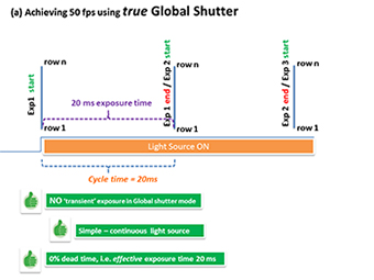
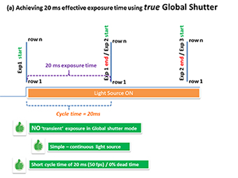
Figure 4 – Timing diagrams illustrating two methods of fulfilling the 50 fps / no spatial distortion conditions of Scenario 1: (a) True Global Shutter, and (b) Rolling Shutter in Simulated Global Exposure Synchronization configuration.
True Global Shutter
The timing diagrams in Figure 4 contrast each method of fulfilling these acquisition conditions. In true Global Shutter, Figure 4 (a), since there is no transient phase of the exposure cycle, all pixels begin the exposure time simultaneously and the input exposure time of 20 ms also defines the effective exposure time with a 0% dead time, fulfilling the 50 fps condition. At the end of the first exposure, the charge from each pixel is transferred into the readout nodes of each pixel from which readout can occur. Meanwhile the subsequent image is free to begin immediately. Furthermore this approach is extremely simple to configure in that a continuous light source may be used and it is not necessary to use any of the Fire TTL outputs from the camera to synchronize a light source.
Simulated Global Exposure Synchronization (using Rolling Shutter)
However, to achieve a cycle time of 20 ms in rolling shutter and ensure that the light source is only activated outside of the transient phases, it is necessary to use the simulated global exposure synchronization method, illustrated in Figure 4 (b). An input exposure time of 20 ms only yields an effective exposure time of 10 ms, i.e. a 50% dead time. Thus the photon signal per cycle will be half of that acquired in true global shutter, from the same frame rate of 50 fps. Furthermore, the simulated global exposure synchronization approach is more complicated in terms of requiring a pulsed light source, synchronous to the ‘FIRE ALL’ TTL from the camera.
Looking towards faster frame rates, the simulated global exposure approach does however carry the advantage of being able to push beyond the 50 fps (full frame) limit of true global shutter mode. In doing so though, the only option is to proportionally deplete the effective exposure time. For example, to achieve a cycle time of 12.5 ms (80 fps), the effective exposure time would be only 2.5 ms, a 80% dead time. At 100 fps, this mode becomes unusable, in that the effective exposure time is zero.
To exceed 50 fps full frame in true global shutter mode, one needs to use an alternative ROI. For example, consider an application that requires a target frame rate of ~ 100 fps. The HD (1920 x 1080) ROI in true global exposure yields a frame rate of 97 fps with 0 % dead time. The HD ROI size applied to rolling shutter in simulated global exposure mode at 100 fps carries a 50% dead time, i.e. 5 ms for readout and 5ms effective exposure time.
Note, since overlap readout is required to maximize frame rate, Global Clear cannot be used with Rolling Shutter mode.
Scenario 2 – Targeting an effective exposure time in absence of peripheral device.
This scenario is similar to scenario 1, except that now the aim is to achieve a 20ms effective exposure time from the full resolution of the sensor, while avoiding any spatial distortion from the rolling shutter effect. Again, since it is not required to synchronize to a peripheral switching device, the ‘overlap’ mode of operation may be used in both rolling and global shutter.
Targets:
Assumptions:
True Global Shutter
The timing diagrams in Figure 5 compare each method of fulfilling these acquisition conditions. In true Global Shutter with overlap, Figure 5 (a), since there is no transient phase of the exposure cycle, all pixels begin the exposure time simultaneously and, as per scenario 1, the input exposure time of 20 ms also defines the effective exposure time condition with a 0% dead time, yielding 50 fps. Again, this approach is very simple to configure in that a continuous light source may be used and it is not necessary to use any of the Fire TTL outputs from the camera to synchronize a light source.
Simulated Global Exposure Synchronization (using Rolling Shutter)
However, to achieve an effective exposure time of 20 ms in rolling shutter and ensure that the light source is only activated outside of the transient phases, it is again necessary to use the simulated global exposure synchronization method, illustrated in Figure 5 (b). An input exposure time of 30 ms is required to give an effective exposure time of 20 ms, yielding a 33% dead time. Thus, the frame rate is reduced to only 33 fps. Again, the simulated global exposure synchronization approach is more complicated in terms of requiring a pulsed light source, synchronous to the ‘FIRE ALL’ TTL from the camera.
The simulated global exposure approach is further complicated if it is required to make use of a region of interest whilst targeting the same effective exposure time. One needs to know the size and exact position of the ROI in order to ascertain the duration of the transient phases of the exposure cycle, in order that the correct input exposure time can be entered into the acquisition software. Unfortunately this is not trivial to calculate.


Figure 5 – Timing diagrams illustrating two methods of fulfilling the 20 ms effective exposure time / no spatial distortion conditions of Scenario 2: (a) True Global Shutter, and (b) Rolling Shutter in Simulated Global Exposure Synchronization configuration.
Scenario 3 – Synchronizing to a fast peripheral device: Fire TTL output from camera to trigger light source
In this scenario, the aim is to synchronize to a fast peripheral device, such a z-stepper or illumination wavelength switcher. Since it is required to synchronize to a peripheral switching device, the ‘overlap’ mode of operation may be implemented in global shutter mode, but must be avoided in rolling shutter mode for the reasons of best practice mentioned earlier. Here we will examine one use of true global shutter and two uses of rolling shutter, only one of which will avoid spatial distortion.
Targets:
Assumptions:
True Global Shutter
The timing diagrams in Figure 6 compare each method of fulfilling these acquisition conditions. In true Global Shutter with overlap, Figure 6 (a), since there is no transient phase of the exposure cycle, all pixels begin the exposure time simultaneously, and the input exposure time of 20 ms also defines the effective exposure time, the Fire 1 output from the camera activating the light source for this same duration. Note, it is possible to use Fire 1, Fire n, ‘FIRE ANY’ or ‘FIRE ALL’ in global shutter, each providing the exact same trigger timing. At the end of the first exposure, the charge from each pixel is transferred into the readout nodes of each pixel from which readout can occur. At this point, a delay of 5 ms is required for the movement of the peripheral device. However, immediately after this the second exposure can start, even though the readout of the first exposure is still progressing from the readout nodes. This is the benefit of overlap mode in global shutter. Use of true global shutter therefore results in a very short cycle time of only 25ms, yielding 40 fps, and an 20% dead time. This approach is extremely simple to configure in that the exposure time input directly defines Fire output of the camera, which in turn directly defines the period of illumination, for any ROI size.
Note that while use of a pulsed light source is assumed here, synchronization to a moving peripheral device can also be carried out with a continuous light source if required, since true global shutter will purge light-induced charge from the active photodiodes of the sensor between camera exposures. This is not possible in the rolling shutter modes of operation shown below, which must always use a triggerable pulsed light source.
Simulated Global Exposure Synchronization (using Rolling Shutter)
However, to achieve an effective exposure time of 20 ms in rolling shutter and ensure that the light source is only activated outside of the transient phases, it is again necessary to use the simulated global exposure synchronization method, illustrated in Figure 6 (b). The Global Clear function is used in order to reduce dead time in this configuration.
Since this approach must be configured in non-overlap mode for rolling shutter use, it is required to wait until the end of the Exposure 1 transient readout period before beginning the Exposure 2 exposure activation period. Due to this 10 ms of overall transient exposure readout time per cycle, the overall cycle time is extended to 30 ms. Given that the light source is on for only 20ms, this represents only a 33% dead time. As such, the frame rate is reduced to 33 fps.
Illuminating over the Complete Exposure Cycle of Rolling Shutter
The timing diagram in Figure 6 (c) illustrates a configuration whereby the ‘FIRE ANY’ TTL output from the camera is utilized to trigger the light source throughout the whole duration of the Rolling Shutter exposure cycle, including a total of 20 ms of ‘transient’ exposure activation/readout periods. As such, this configuration is not designed to emulate a global shutter condition. While all rows will receive the same overall effective exposure time of 20 ms, a notable disadvantage is that the sample itself has had to receive 30 ms of illumination in order to achieve this. This represents a 50% increase per frame in the amount of photo-bleaching of the sample, compared to the previous configurations. After factoring time for the peripheral device switching, the overall cycle time becomes 35ms, yielding 28.6 fps, still significantly slower than that achievable in true global shutter. The dead time becomes 43%.
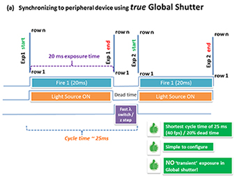
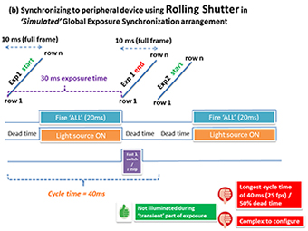
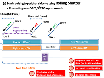
Figure 6 – Timing diagrams illustrating three methods of synchronizing to a peripheral device, given the conditions described in Scenario 3, whereby a FIRE output from camera is used to trigger light source: (a) True Global Shutter, (b) Rolling Shutter in Simulated Global Exposure Synchronization configuration, and (c) Rolling Shutter using Fire ANY TTL output to illuminate during entire rolling shutter exposure cycle (i.e. will not avoid spatial distortion).
Conclusions
Appendix: Comparing Signal to Noise Ratio between True and Simulated (Rolling) Global Exposure
Scenario 1 of this paper set out to achieve 50 fps frame rate from the full resolution of the sensor, while avoiding any spatial distortion from the rolling shutter effect. One of the key conclusions was that this could be achieved in true global shutter with a 0% dead time (and needing only a continuous light source), whereas a 50% dead time (and a triggerable pulsed light source) is required when using simulated global (rolling) exposure.
This comparison was set up and measured using a Zyla 5.5 sCMOS camera in both modes of operation. The camera was mounted on top of a light tight imaging rig, in which a bottom mounted LED illuminates a diffuser, providing the imaging target. The intensity of the LED illumination can be varied from a simple attenuator, and it may also be pulsed on/off from the relevant Fire output of the camera.
Figure 7 shows images recorded at two different illumination light levels, corresponding to (a) ~ 20 incident photons per pixel and (b) ~ 4 incident photons per pixel, recorded for both true global and simulated global modes of acquisition at the target frame rate of 50 fps.
If the signal is truly shot noise limited, i.e. the signal is intense enough to be clear of the read noise floor, then the SNR difference between true and simulated global exposure modes should be dictated by the difference in dead time, thus amount of photons collected between the two modes. When targeting 50 fps, we expect a 0% dead time in true global shutter (20 ms effective exposure time) and a 50% dead time for simulated global shutter (10 ms effective exposure time). This factor x2 difference in collected photons should result in a factor difference in measured SNR of square root 2 (~1.4).
It is clear from figure 7 (a), that the measured SNR difference of x1.4 indicates that even the relatively low light signal of 20 photons per pixel is sufficiently clear of the read noise floor, such that the higher read noise from global shutter is not a factor. This means that in this case true global shutter can be used to yield a significantly higher SNR, equivalent in performance to x2 higher ‘effective QE’.
Figure 7 (b) shows images measured at an extremely weak light level, which can be considered to be very close to the read noise detection limit. It is expected that at such levels, the higher read noise floor of global shutter mode would factor more prominently in a SNR comparison. Indeed, while the true global shutter SNR remains higher due to the fact that double the amount of photons are collected, the factor difference between the two modes has reduced to x1.15.
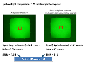
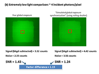
Figure 7 – Signal to Noise Ratio measurements, comparing ‘True’ vs ‘Simulated’ global exposure methods (the latter using rolling shutter) to achieve the conditions presented in Scenario 1, at illumination levels of (a) ~ 20 incident photons per pixel and (b) ~ incident photons per pixel.

© Oxford Instruments 2026
