Resources
 Part of the Oxford Instruments Group
Expand
Collapse
Part of the Oxford Instruments Group
Application Notes
Author: Andor
Published: 10 Feb 2021 · Last updated: 15 Jul 2025
Tags: tier-3-tools-for-plasma
Laser induced fluorescence or LIF is a long established technique for diagnosis of the makeup and characteristics of plasmas [1-4]. The presence and concentration of a species may be determined from its characteristic fluorescence when it is excited by a laser source. Typically a laser excitation wavelength is chosen that is well matched to an optical absorption transition of the species, and a narrow band filter is used to select the fluorescence in the region of characteristic wavelengths associated only with that species whilst rejecting background. Planar Laser Induced Fluorescence or PLIF is a variant of the basic technique which confines the excitation illumination to a well-defined sheet (or thin plane) within the plasma thus enabling the acquisition of spatial information on the concentrations of the species. The PLIF signal is typically captured on a 2D CCD imaging sensor. This application note outlines some examples of setups used for PLIF, the type of equipment involved and highlights some of the information it can provide.
PLIF is a technique used widely to characterise the evolution of molecular species within plasma plumes. Using characteristic fluorescence emission from the species, the spatial distribution over time of the evolving species can be mapped out [3, 5]. ICCD cameras are often used as these offer accurate time gating and synchronisation with the pulsed excitation source (usually a laser). The types of plasmas investigated include short lived transient plasmas generated from pulsed lasers or pulsed electrical discharges, combustion of fuels, magnetically confined plasma (MCF) and radio-frequency (rf) generated plasmas.
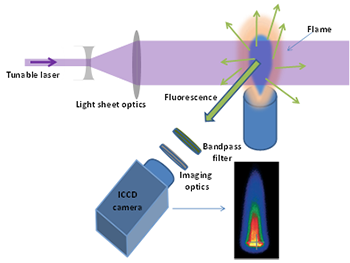
Figure 1: Schematic of a setup for PLIF measurements
A basic schematic of a PLIF setup is shown in figure 1. The excitation lasers used are typically pulsed and tunable with wavelengths that can be well-matched to the absorption of an optical transition within the species of interest. A Q-switched Nd:YAG pumped dye laser is an example of such a laser source. Central to the PLIF technique is accessing the plane of interest within the sample plasma. There are different schemes for achieving this aim, such as
The first approach is the most common method.
The fluorescence generated in the plane is imaged (perpendicular to the plane) on to a 2D CCD camera with imaging optics. Narrow bandpass filters are typically placed in this optical path to select those particular wavelengths identifying the species of interest whilst rejecting background due to fluorescence from other species and laser scatter.
The most important information that can be deduced is generally the determination of species’ concentration and their temporal and spatial evolution in the plume. However important information on the temperature and pressure within the plasma can be determined in PLIF studies, and when combined with Particle Imaging Velocimetry (PIV) the velocity and flow field dynamics of the species can also be determined. Typical types of species investigated within plasmas and in particular in combustion studies include OH, CH, NO, NH, CN, CO, and O2 radicals as well as excitations within atomic and ionic species. These species are often intrinsic to the plasma but in flow dynamic studies tracer materials with good fluorescence characteristics are added to the main flow material. Examples of the latter are the use of ketones (acetone and 3-pentanone).
One example of the use of PLIF imaging has been in pulsed laser deposition (PLD) [5]. PLD is a powerful technique used to evaporate refractory materials (metals or ceramics) in a vacuum or a background gas atmosphere through the creation of a plasma. The plasma species condense on a substrate where the growth of a thin film takes place. As part of the process to optimise the films’ growth and properties, researchers are particularly interested in the evolution of the different species within the plume and correlating these characteristics to the properties of the films such as film stoichiometry. Figure 2 shows LIF images of an expanding plasma plume at different delays in time.
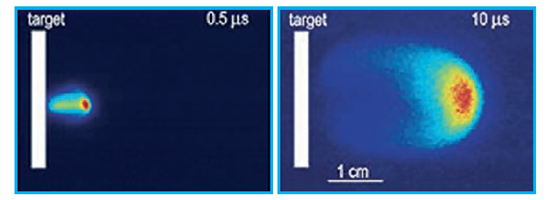
Figure 2: LIF images of an expanding plasma plume taken with an ICCD camera at two different delay times 0.5 µs and 10 µs.
A major area of application of PLIF is in combustion studies. Studies on Flow Dynamics often combine both PLIF and PIV measurements to characterise the transport properties within the flame or plume, the turbulence, temperature, pressure as well as the concentrations of species. Some specific variants of the techniques are referred to as OH-PLIF, CH-PLIF, Two photon CO-PLIF, TR-PLIF and CW-PLIF.
An example setup for PLIF measurements on laser produced plasma (LPP) is shown in figure 3 (after the work of Martin et.al. [5]). This illustrates the generation of a transient plasma plume with a pulsed laser as used in PLD deposition. The schematic shows an incoming laser pulse (λ=248 nm, ~30 ns pulse length, fluence ~2 Jcm-2) from an Excimer laser incident on a rotating target which generates an expanding plasma plume. Typical target materials investigated by the QUB group [5] included metals such as Ti, Mg, and Al, and ceramic materials such as YBaCuO as used in superconducting thin films. A light sheet generated with a collimated beam from a Nd:YAG pumped dye laser (Lambda Physik Scanmate 2C) illuminated a slice through the plume. (Laser characteristics were pulse length of ~5 ns and narrow bandwidth FWHM of ~0.15 cm-1.) The collimated beam was passed through an aperture defining a sheet thickness of the order of ~1 mm. Imaging optics consisting of a mirror and lenses captured the fluorescence on to an ICCD camera. Narrow band filters were inserted in this optical path to reject background emissions and scatter.
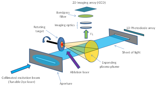
Figure 3: Schematic setup used for PLIF measurements on LPP plasma plumes. A light sheet from a tunable dye laser excited species within a layer in the plume resulting in fluorescence(FL) which was subsequently imaged on to a 2D ICCD camera. In this setup the absorption profile of the dye laser through the plasma was also measured by an in-line linear photodiode array (after [5]).
Dye lasers offer multiple wavelengths and are tunable. This allowed for the selection of excitation wavelengths that were matched to resonant absorption transitions of the species under investigation. Fine tuning of the laser at a given wavelength enabled the observation of Doppler effects within the expanding plume. As an example the dye laser was tuned to access the transitions of the MgI (31P1 – 31S0) species at 285.2127 nm, and the MgII (32P1/2 – 32S1/2) species at 280.2704 nm, in investigations of the ground-state and neutrals within a low-temperature magnesium LPP. PLIF imaging was used to determine the number density distributions for MgI neutrals within the plasm plume; the profiles are illustrated in figure 4 (after [5]). In this case de-tuning of the laser (typically ~300 mÅ) allowed for preferential excitation of the Doppler shifted species laterally. Estimation of the number densities was derived from the resonance broadening of the absorption line shapes.
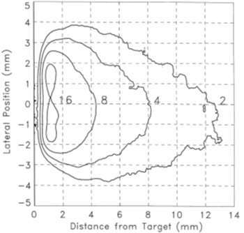
Figure 4: Contour plots of the number density of MgI neutral species within a laser-produced magnesium plasma. The profiles were derived from PLIF images of a plane through the plume with de-tunings of the excitation of ~300 mÅ. The number densities are in units of 1x1014 cm-3 (after Fig. 2 of [5]).
Also evident in the schematic is the capability to translate the illumination plane through the plume thus enabling the build-up of a 3D dataset showing the distribution of the species in three dimensions based on a time series over a range of laser pulses.
A schematic of a PLIF setup as used in combustion studies is shown in figure 5 (after Shimura et. al. [6]). In this group’s work both CH-PLIF and OH-PLIF are carried out simultaneously. Their work investigated local flame structure in turbulent pre-mixed flames. Allied to PLIF they carried out simultaneously stereoscopic PIV measurements in the same plane through the sample as for the PLIF measurements using CMOS cameras. Measurements of the distribution of the OH and CH radicals gave structural information on the flame. The OH shows high concentrations in the burned fuel allowing for OH-PLIF to distinguish between burned fuel and unburned mixture. In contrast the CH radicals are characteristic of the flame fronts and the reaction zones. The excitation sheets of illumination from the different laser sources were formed through the flame using sheet forming optics as shown in the figure (sheet dimensions were typically 200 ?m wide by 30 mm in height). The sheets of light were all coincident.
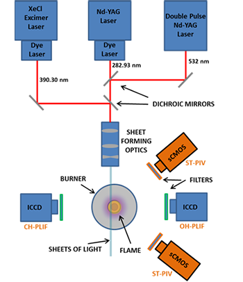
Figure 5: Schematic of an experimental setup to carry out CH-PLIF, OH-PLIF and stereoscopic PIV simultaneously in combustion studies (after figure 1 of Shimura et. al. [6]). The PLIF measurements were made on ICCD cameras whilst those for PIV were on CMOS cameras. The excitation beams at different wavelengths were formed into planes which coincided in the specimen using a series of dichroic mirrors and sheet forming optics.
ICCD cameras were used to capture the PLIF data. For the CH-PLIF, an absorption transition band at 390.30 nm was excited with the output from a dye laser (390.30nm) pumped by an Excimer XeCl laser. An iStar ICCD 1024x1024, 25 mm Gen2 intensifier with UV imaging lens viewed the sample perpendicular to the light sheet. For the OH-PLIF, the excitation at a wavelength of 282.93 nm was provided from a Nd-YAG pumped dye laser and an ICCD camera viewed the light sheet from the opposing side. Filters were placed in front of the cameras to reject the flame emission and scattered light from tracers used in PIV and any other background. These filters were chosen to offer detection in the 420 – 440 nm region for the CH- PLIF fluorescence and the 306 – 320 nm region for the OH-PLIF.
An illustration of typical data captured from PLIF measurements in combustion studies is shown in figure 6. This data is from work by a group at Sandia National Laboratories [7] where CO-PLIF and OH-PLIF were used to probe the detailed structure of turbulent jet flames. In this case two-photon OH-PLIF and single photon OH-PLIF were used to investigate in 2D the forward rate of reaction of:
CO + OH → CO2 + H
An instantaneous measurement of CO-PLIF and OH-PLIF and the reaction rate in a partially mixed methane-air jet flame is shown in the figure. The excitation for the species was provided from two tunable UV lasers at wavelengths of 230 nm for the CO and 285 nm for the OH. Fluorescence from the illuminated plane within the flame was imaged on to two ICCD cameras. Use was made of the gating of the intensifier (400 ns in this case) to assist in the rejection of flame emissions along with the narrow band filters in front of the cameras.
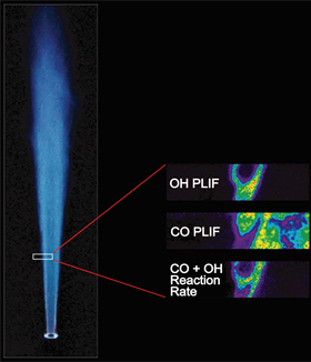
Figure 6: Example of use of OH-PLIF and CO_PLIF imaging to investigate turbulence structure within a flame [7].
An introduction of the PLIF technique for diagnosing plasmas has been outlined with illustrative examples from both PLD and combustion studies. Reference has been made to a few of the many specific variations on the basic technique such as CO-PLIF, CH-PLIF, and two-photon PLIF. The main components required for successful measurements include tunable pulsed lasers, light sheet forming optics, intensified CCD and/or fast frame rate CMOS cameras, and a synchronisation unit. In some high end cameras, the synchronisation unit is an integral part of the camera.
Key to successful measurements in PLIF is the ability to measure at high frame rates (>10 Hz) images taken with high sensitivity and in short temporal windows of a few 100’s of nanoseconds. New intensified sCMOS (ICMOS) cameras are an ideal tool for such measurements offering faster frame rates than the conventional ICCDs, synchronisation and gating capabilities, and high sensitivity where required. This has enabled for faster frame rates to match higher repetition rate excitation lasers. Allied to this capability is the ability for Intensified sCMOS cameras to take dual images with high temporal resolution as required for many PIV measurements. PIV is a technique which is often used in tandem with PLIF in flow dynamic studies of evolving molecular species as for example in combustion processes.
The information and images provided by various groups including Dr JH Frank, and Dr RJ Sigurdsson of Sandia Nat. Lab., and Prof. MG Long and Dr SA Kaiser of Yale University, are gratefully acknowledged.

© Oxford Instruments 2026
