Resources
 Part of the Oxford Instruments Group
Expand
Collapse
 Part of the Oxford Instruments Group
The ultra-low value of ~1 electron rms read noise available from today’s sCMOS cameras is entirely unprecedented, and dramatically outperforms even the best CCD cameras. Read noise is an important contributor to the noise floor detection limit of a camera, but the thermal noise component (darkcurrent) is also very important. For CMOS based cameras, even modest exposure times can result in a significant amount of darkcurrent noise that impacts imaging quality. This makes it important to consider dark current as well as read noise in respect to minimising the overall noise floor of a camera.
Although the design and production of the sensor will dictate the baselevel of dark current of the camera, one of the ways we can supress dark current is by cooling the sensor. Andor's sCMOS cameras are therefore designed to have the lowest possible dark current through use of effective sensor cooling. In fact, the Andor Sona and Marana sCMOS cameras are the only commercially available CMOS cameras with permanent vacuum technology. This permits the deepest level of thermoelectric cooling (to -40°C and -45°C respectively) and thus minimizes the detrimental influence of dark noise.

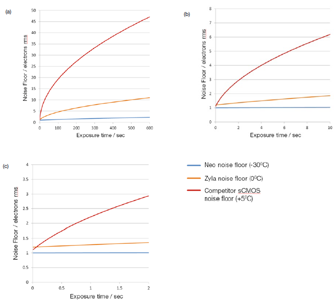
Figure 1 - Plots of sCMOS noise floor (read noise and dark noise combined in quadrature) versus exposure time, at sensor cooling temperatures of +5°C measured from competitor's sCMOS camera vs. 0°C and -30°C (measured from Zyla and Neo sCMOS respectively). Plots are shown over three ranges of exposure time: 0 - 2 sec, 0 - 10 sec and 0 - 600 sec.
Theoretical plots of noise floor versus exposure time are shown in figure 1 for the sCMOS sensor CIS2051 at three different cooling temperatures, +5°C, 0°C and -30°C. The parameters used in determining the overall noise floor are based on a typical read noise 'baseline' of ~ 1 electrons, combined with the measured typical darkcurrent of the CIS 2051 sCMOS sensor at each of the temperatures, values for 0°C and -30°C from the Andor Zyla and Neo sCMOS cameras respectively. The darkcurrent value used for the sensor at +5°C has been taken from the datasheet available from another camera manufacturer. Combined noise is calculated in quadrature, i.e. using the 'square root of the sum of the squares method'.

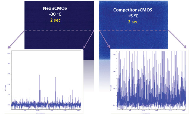
Figure 2 - Thermal noise can sacrifice the sCMOS low detection limit as illustrated here. Low light images recorded with a Neo sCMOS at -30°C versus a competing sCMOS @ +5°C, Shown with same relative intensity scaling; 2 sec exposure time; 560MHz readout speed. Comparative line intensity profiles from a single row are also shown.
For the example shown here with the exposure range up to 2 sec, the low noise floor can be observed to be notably sacrificed by almost x2 at the higher temperature of +5°C. In contrast, by cooling to -30°C the ~1 electron noise floor can be maintained. If the exposure time was extended to 10 sec, the noise floor associated with +5°C is significantly compromised to a value greater than 6 electrons, i.e. x6 greater than the read noise, whereas the noise is maintained to values less than 1.5 electrons with deeper cooling.
For very low light measurements, not every experiment demands very short exposures. Sometimes we need to extend exposures to 500 milliseconds to 1 second to capture the weak signals. For others as in chemiluminescence detection, it can sometimes be required to have exposures extending to 10 minutes and beyond. At 600 sec, unless deep cooling is applied, the thermal contribution to the noise floor would become excessively large, shown in graph C as reaching > 45 electrons at +5°C. Holding the cooling temperature at -30°C would result in the noise floor being held at a more modest 2.4 electrons over this extensive exposure period.
Figure 2 shows dark images of 2 second exposure, taken with Neo sCMOS versus a competitor's sCMOS camera (with the same sensor type that runs at + 5°C. The same relative intensity scaling (in terms of absolute electrons) is used to display each. The detrimental effect of high darkcurrent due to operation of the sCMOS sensor at higher temperatures is clear to see. Deep cooling therefore can be seen to extend the useable exposure range of sCMOS sensors such as the CIS2051 and other popular sensors such as the CIS2020 (Zyla 4.2PLUS) and GS2020BSI (Sona-6 and Marana-6). However, even with deep cooling, the recommendation for long exposure applications over many minutes are deep cooled CCD cameras such as the iKon-M CCD, providing the best Signal to noise ratio, while the slower speeds are not a factor.
CMOS sensors are particularly susceptible to what are called “hot pixel” blemishes. These are spurious noise pixels that have significantly higher darkcurrent than the average pixels. They can easily be observed, are detrimental to the image and could be seen for example like a bright spear through an otherwise perfect 3D confocal image.
| Sensor Operating Temperature (°C) | Number of Hot Pixels with a value of >2e-/p/s |
| +5°C | 28,500 |
| -30°C | 1,800 |
Table 1 - Typical number of hot pixels (i.e. higher than average darkcurrent pixels) of the 5.5 Megapixel 2051 sCMOS sensor that show darkcurrent greater than 2 e-/pix/sec at cooling temperatures of +5°C and -30°C.
Thankfully, we can use deep TE cooling of the sensor to dramatically reduce the population of hot pixels within the sensor, meaning that these pixels be used for quantitative imaging. Table 1 shows that the typical number of pixels with higher-than-average darkcurrent can be dramatically limited in practice through cooling of the sensor, meaning that they are not required to be treated by interpolation filters. In the example shown here- deep cooling has reduced these pixels that require interpolation or other correction methods to be reduced to <0.03% of the total pixel population. A similar profile is observed for the GS2020BSI sensor. We really want to avoid using interpolative filters and impacting the integrity of the image data as a general principle. Indeed such interpolation applied to pixel blemishes can be detrimental in some applications that depend on total quantitative integrity over a limited set of pixels, for example in localization based super-resolution microscopy (such as PALM and STORM techniques). Certain blemishes may also not be corrected if a cluster happen to appear adjacent to each other.

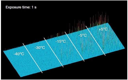
Figure 3 (a) - Blemishes at different temperatures for 1 sec exposure.
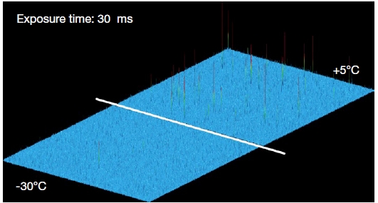
Figure 3 (a) shows a 3D intensity plot of the same region of a sCMOS CIS2051 sensor at a number of different cooling temperatures, each recorded with only 1 sec exposure time in rolling shutter mode. It is clear that cooling to -30°C and beyond is highly effective in reducing the occurrence of hot pixel spikes, thus offering both an aesthetically cleaner image and a greater proportion of useable and meaningful pixels. This in turn means that significantly fewer pixels need be treated using a nearest neighbor median replacement algorithm. Even using very short exposure conditions of 30 ms, there are still significant numbers of hot pixels present at higher cooling temperatures, as illustrated in figure 3 (b).

Figure 3 (b) - Blemishes at -30°C vs +5°C for 30 ms exposure
In the sections above we have seen that moderate and deep cooling can be used to effectively minimize the overall noise floor and obtain the lowest possible detection limit. Cooling also reduces the amount of hot and other non-uniform pixels that would otherwise need correction or interpolative filters applied. A further consideration is that some optical configurations are sensitive to vibrations from the camera fan, such as patch clamp, combined optical/AFM set-ups, or super-resolution or other fast imaging at high magnifications.
Andor cameras have several features to allow the benefits of deep cooling, and minimise/eliminate of vibration.
The Zyla 4.2PLUS and newer models of Zyla 5.5 feature a low vibration fan to help minimize fan-induced vibrations. A water cooled version of the Zyla is also available specifically for vibration critical experiments.
The Neo 5.5 can be set for air cooling or liquid cooling. For air-cooled running the fan speed can be adjusted between 2 speeds. Additionally, the deep cooling advantage of Neo means that the internal fan can be turned off for a period of time. Liquid cooling can also be used to eliminate fan-induced vibrations.
'Liquid cooling' through the camera allows minimization of vibration while still stabilizing at -40°C. Alternatively, if complete vibration free operation is required without water cooling, the Neo fan can turned off for a limited period of time, during which the camera is passively cooled. Table 2 shows typical fan-off durations that apply when the Neo camera is operated in a + 25°C ambient environment.
| Sensor Readout Speed | Selected Sensor Temperature | Duration Before Fan Is Forced On |
| 560 MHz | 0°C | 60 minutes |
| 560 MHz | 5°C | 79 minutes |
| 560 MHz | 15°C | 93 minutes |
| 560 MHz | -15°C | 9 minutes |
| 560 MHz# | -30°C | 5 minutes |
| 200 MHz | -15°C | 18 minutes |
| 200 MHz | -30°C | 12 minutes |
Table 2 - Examples of what fan-off durations achievable across a range of cooling temperatures and readout speeds when operating Neo sCMOS in an ambient environment of 25°C.
As with the Neo 5.5, the Sona and Marana back-illuminated sCMOS cameras can be configured in air cooled or liquid cooled formats. Under air cooling, 2 fan speeds and switching the fan off for a short duration is possible. Depending on imaging parameters it is possible to run the Sona and Marana cameras for minutes before the fan with switch back on. This provides a convenient alternative to water cooling to eliminate vibration- providing the experiments are short and time is available for the sensor to return to the set temperature before subsequent images are acquired. Liquid cooling provides the most effective deep cooling and elimination of vibration.
Date: Dr Alan Mullan and Dr Colin Coates
Author: December 2021
Category: Technical Article
