Resources
 Part of the Oxford Instruments Group
Expand
Collapse
Part of the Oxford Instruments Group
Technical Article
Author: Dr Alan Mullan & Dr Jo Walters
Published: 01 Mar 2023 · Last updated: 13 Mar 2023
These are exciting times for electronic imaging. The imaging camera is one of the most critical components in many experiments. We can now observe single photons in experimental physics and quantify single molecules in experimental biology. We can view processes within whole small animals, experiment on organoids and study the complexities of neural networks in the brain. We can watch chemical and biological processes on nanosecond timescales.
Understanding the process of how the light images are captured on the different sensors available will help to guide our choice of camera. In this article we aim to provide an understanding of the basics of light detection so you can understand and compare technical specifications. This will help you to select a suitable detector for specific applications. We are constantly developing new technology for scientific cameras. This guidance is based on current developments in 2023.
Scientific digital cameras are based on two sensor technologies: the original CCD-based cameras, including the EMCCD and ICCD. Then there are CMOS cameras including sCMOS or scientific CMOS. The camera types have different strengths and weaknesses making each suitable for specific applications. These are covered in depth in other articles within our learning centre.
The first scientific cameras were developed in the 1960s and the CCD or Charge Coupled Device is a mature technology. sCMOS is relatively new, developed in the 1990s on the back of innovations in mobile phone sensor technologies, and is the new state of the art. However CCD cameras are still preferred for some types of experiments. What makes these scientific cameras different to a standard camera is that they have a uniform response to light. That is to say that changes in light may be used as the basis for quantitative measurements such as rates or concentrations. So, how do we compare different cameras and select the most suitable one for a certain application.
Scientific cameras will have a product data sheet or technical specifications that will provide information on many different parameters. In the following paragraphs we will look at some of these technical terms and explain what the important ones are and what they may mean for your imaging experiments.
The role of the camera is to convert light of a certain wavelength into a useable digital signal as efficiently as possible. This parameter is often expressed in terms of the Quantum Efficiency (or QE). It is the percentage of incident photons that the device can convert into electrons. i.e. 80% QE at a certain wavelength would mean that if there was a signal of 100 photons, 80 of these would be captured and converted into a signal by the camera.
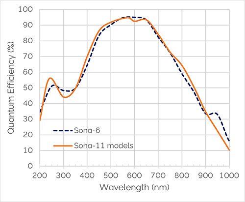
Here is an example showing the QE profile of Sona sCMOS cameras. You can see that they have exceptionally high QE between 450 and 700nm. When choosing a camera, you would choose a sensor showing high Quantum Efficiency over the wavelength range you require.
The sensitivity of a camera is the minimum light signal that can be detected. By convention we equate that to light level falling on the camera that produces a signal just equal to the camera's noise. Hence the noise of a camera sets an ultimate limit on the camera sensitivity. Digital cameras are therefore often compared using their noise figures. Noise derives from a variety of sources principally:
Another noise source which is often overlooked is the excess noise that arises from the camera's response to light signal, which is known as the Noise Factor.
Dynamic Range is a measure of the maximum and minimum intensities that can be simultaneously detected in the same field of view. It is often calculated as the maximum signal that can be accumulated, divided by the minimum signal. This equates to the noise associated with reading the minimum signal. It is commonly expressed either as the number of bits required to digitise the associated signals or on the decibel scale.
A camera's ability to cope with large signals is important in some applications. When a CCD camera saturates it does so with a characteristic vertical light streak, called Blooming. No useful measurements can be made if the sensor is saturated.
A camera's signal-to-noise ratio (commonly abbreviated S/N or SNR) is the amount of signal above the background noise level.
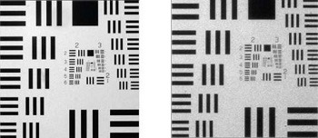
Digital cameras have finite minimum regions of detection (commonly known as Pixels), that set a limit on the Spatial Resolution of a camera. However the spatial resolution is affected by other factors such as the quality of the lens or imaging system. The limiting spatial resolution is commonly determined from the minimum separation required for discrimination between two high contrast objects, e.g. white points or lines on a black background. Contrast is an important factor in resolution as high contrast objects (e.g. black and white lines) are more readily resolved than low contrast objects (e.g. adjacent gray lines). The contrast and resolution performance of a camera can be incorporated into a single specification called the Modulation Transfer Function (MTF).
The Frame Rate of a digital camera is the fastest rate at which subsequent images can be recorded and saved. Digital cameras can readout subsections of the image or bin pixels together to achieve faster readout rates, therefore typically two frame rates are defined, one is a full frame readout rate and the other is the fastest possible readout rate.
Cameras to some degree all exhibit blemishes which affect the reproduction of the light signal. This is due to several variables, such as Gain variations across the sensor and regional differences in noise. These are compensated for with sophisticated software correction in more recent models.
In this section we compare CCD, EMCCD and ICCD to sCMOS cameras and consider the applications suited to each of these camera technologies.
![]()
In CCD based detectors – CCD, EMCCD, and ICCD - a silicon diode photosensor (often called a Pixel) is coupled to a charge storage region which is connected to a readout region and amplifier. Incident photons generate electronic charges, which are stored in the charge storage region. The transmission and absorption properties of the silicon then define the spectral response of the detector.
In a CCD, there is typically only one amplifier at the corner of the entire array. The stored charge is sequentially transferred through the parallel registers to a linear serial register, then to the read-out amplifier. This process takes time. And so time is a limiting factor in CCD sensors. CCD have relatively slow readout speeds. If we want fast readout, CMOS and sCMOS cameras can achieve high frame rates.
![]()
In sCMOS detectors, each photosensor or column of photosensors has an amplifier associated with it. A row of pixels can be readout in parallel. An sCMOS device is essentially a parallel readout device and therefore can achieve higher readout speeds. To achieve the parallel readout the sCMOS amplifier uses multiple amplifiers, each with its own gain, linearity and noise performance variation.
sCMOS cameras were developed in partnership with Fairchild Imaging – part of British Aerospace (BAe) and German camera company PCO (Excelitas PCO). The resulting sCMOS detectors are superior in almost all aspects to CCD sensors for most applications. In this article we do cover some of the experiments that are still preferable with an ICCD or EMCCD or CCD.
EMCCD cameras allow exceptional sensitivity and high readout speeds. EMCCD (electron multiplying CCD) cameras are relatively new types of cameras which allow high sensitivity measurements to be taken at high frame rates. The operation and properties of these cameras are outlined.
The EMCCD has essentially the same structure as a CCD with the addition of a very important feature. The stored charge is transferred through the parallel registers to a linear register as before but now prior to being readout the charge is shifted through a multiplication register, in which the charge is amplified. A signal can therefore be amplified above the readout noise of the amplifier and hence an EMCCD can have a higher sensitivity than a CCD.
![]()
EMCCDs use similar structures to CCDs and have similarly long minimum exposure times.
ICCD (intensified CCD) cameras combine an image intensifier and a CCD camera and are useful for the lowest light situations. In addition, the image intensifier has useful properties which allow the camera to have very short exposure times (in the nanosecond region).
Intensified CCD Cameras can achieve ultra short exposure times. In an ICCD, the Image Intensifier has a photosensitive surface (Photocathode) which captures incident photons and generates electronic charges that are sensed and amplified.
The photocathode is similar in nature to the photosensitive region of Photomultiplier tubes (PMTs) that are widely used in confocal microscopes and spectrometers. When photons fall on a photocathode they utilize the energy of the incident photons to release electrons. The liberated electrons are then accelerated toward an electron multiplier composed of a series of angled tubes known as the Micro-Channel Plate. Under the accelerating potential of a high voltage, the incident electrons gain sufficient energy to knock off additional electrons and hence amplify the original signal. This signal can then be detected using a CCD.
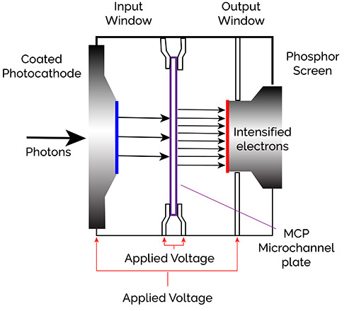
The ICCD can achieve short exposure times by using a pulsed gate voltage between the photocathode and MCP. By applying a small positive voltage, electrons liberated by the photocathode can be suppressed and hence not detected. By switching the voltage to a negative voltage, electrons from the photocathode are accelerated across the gap to the MCP where they can be amplified and detected. By applying a suitable short voltage pulse the intensifier can therefore be effectively turned on and off in sub nanosecond intervals. ICCD cameras find uses in applications where short exposure times or gating is required such as plasma studies, time resolved fluorescence or quantum optics.
sCMOS cameras are now the camera of choice for most scientific applications. They have been engineered so there is no compromise between speed, resolution, field of view, dynamic range, and sensitivity. We can use them in a wide range of applications for developmental biology and neurophysiology, for solar astronomy and dynamic X-ray imaging.
CCD cameras remain preferable for specialist applications requiring a large field of view, high dynamic range and high sensitivity of weak signals captured over long exposure times of minutes or hours such as Astrospectroscopy, Astronomy, Neutron Radiography, luminescence, Plant Science Research and Biochip reading.
An EMCCD camera works best in applications requiring exceptional sensitivity - we can now obtain single photon sensitivity. This may be coupled with high speed - nanosecond timescales - making it ideal for (in life science) fluorescence microscopy including super-resolution microscopy and (in physical sciences) Ultra Fast Spectroscopy, Single Molecule Spectroscopy and Chemical Mapping.
ICCD cameras are used for Plasma Studies, Time Resolved Fluorescence, Photoluminescence and Raman.
With this knowledge, we direct you to the specification sheets for each camera available on the Andor website.

© Oxford Instruments 2026
