Resources
 Part of the Oxford Instruments Group
Expand
Collapse
Part of the Oxford Instruments Group
Application Notes
Author: Andrew P. Carpenter
Published: 01 Dec 2025 · Last updated: 07 Jan 2026
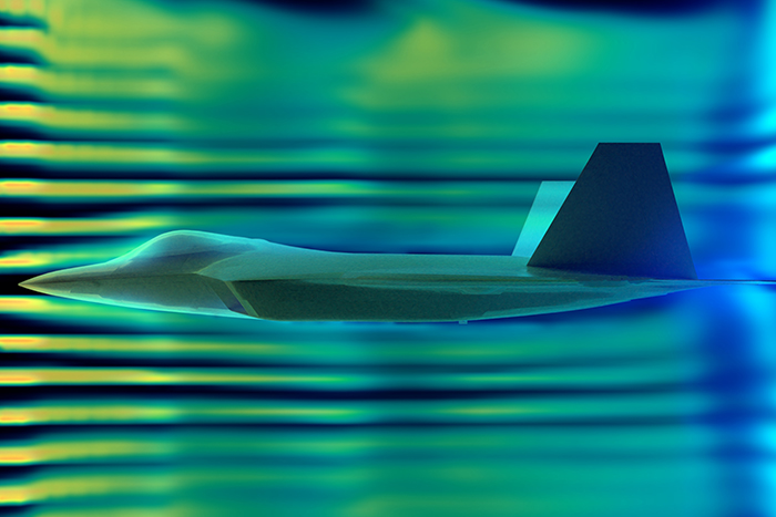
Turbulent flows around supersonic and hypersonic vehicles are necessary to understand as they can lead to the degradation of the walls of spacecraft and high-altitude aircraft. Thus, characterizing material and aircraft design performance under these conditions becomes important. To experimentally create supersonic and hypersonic flow conditions, scientists can turn to shock tubes and highly specialized wind tunnels to create the non-equilibrium flow conditions that are representative of flight conditions such as supersonic flight or atmospheric re-entry. Examples of such facilities can be found in academic institutions1 and larger government agency laboratories2.
Characterizing supersonic and hypersonic flows can be done using optical diagnostics ranging from the UV to the near-infrared (NIR) – with methodologies including absorption spectroscopy, CARS, and PLIF, MTV, and PIV to name a few.3-5 These diagnostic tools enable the study the chemical composition and reactions under different flow conditions, as well as provide insight the flow dynamics themselves and how gas propagates around vehicular structures.
Herein we present Andor’s intensified sCMOS camera as a technology solution capable of providing precision temporal control for fast imaging and double frame imaging experiments (ex. PIV and MTV) of supersonic and hypersonic systems before highlighting several examples.
Intensified camera technology places an image intensifier in front of CCD or sCMOS sensors, with the intensifier unit providing an optical gating mechanism possessing nanosecond precision. At Andor these cameras are labeled underneath the iStar camera line. Intensified cameras are commonly grouped by their image intensifier’s photocathode material – multi-alkali (Gen-II) and GaAs (Gen-III) based materials. The photocathode defines the camera’s sensitivity with Gen-II cameras being optimized for UV detection, with sensitivity down to ~ 125 nm, and Gen-III cameras being optimized for the VIS and NIR spectral regions. More extensive introductions into intensified camera gating mechanisms and optimizing their performance exist within Andor’s Learning Center. Understanding that iStar cameras are optimized for either the UV or VIS-NIR spectral ranges and have nanosecond gating capabilities is sufficient to explore the application of the iStar sCMOS camera in the context of Supersonic and Hypersonic studies.
Specific to the iStar sCMOS camera there are a few inherent advantages that stem from using a sCMOS sensor behind the image intensifier instead of a CCD. In an sCMOS sensor, photoelectrons are generated inside pixels when photons are absorbed. These photoelectron signals are readout at the pixel level, and columns of pixel signals are processed in parallel, leading to a significant increase in frame rate capabilities (> 10x) over intensified cameras built with CCD sensors. In addition to faster frame rates the pixel level readout also provides opportunities for fast double-frame imaging measurements (ex. PIV or MTV). In the interest to studying the dynamics in super- and hypersonic flows, double frame imaging provides a method of calculating gas velocities across the entire image plane.
We expand on the double-frame imaging experiments as it can be a powerful tool in the experimental toolbox. Using these methodologies, velocity measurements can be made by analyzing changes in images recorded microseconds, and faster, apart. In any double-frame imaging experiment the interframe gap (time between images) is dependent on how quickly photoelectron charge can be moved of the sensor so another image can be acquired. Before sCMOS cameras, interline CCDs were used to take one pair of images ~2 us apart. However, these cameras weren’t fully optimal due to long readout time, issues with differing exposure times between the two images, and inefficiencies in the masked off region creating image distortions. With the introduction of global shutter sCMOS cameras this changed. Andor’s iStar sCMOS has a sensor that move photoelectron charge off the image sensor within 2 us, establishing an initial minimum interframe gap. While there is a similar interframe gap as the old interline CCDs, there are no inefficiencies from masked pixel columns or differing exposure times.
With the right experimental set-up it is possible to push the interframe gap into a sub-microsecond temporal regime (Figure 1). In a “standard” double-image experiment the camera’s charge transfer mechanism limits the image delay to 2 us. If a pulsed nanosecond laser system is used, flashing the system for short periods of time, than the temporal delay between two pulse pairs can bring the image delay below interframe gap. Bringing “Frame 1’s” pulse into the interframe gap, and approaching the start of Frame 2, can shrink the image delay to ~ 100 ns. With the iStar sCMOS a pulsed laser isn’t strictly necessary, with the use of a pair of nanosecond optical gates capable of bringing the image delay into the interframe gap.
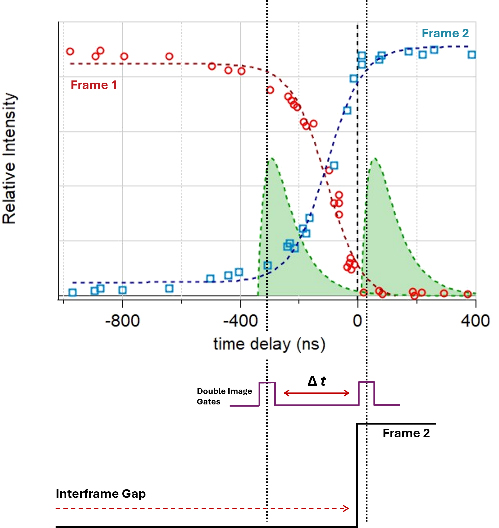
Figure 1. Example of how the use of double image gates with an intensified sCMOS cameras can be used to provide sub-microsecond time delays for double-frame imaging. Normalized intesnity of a single pulse measured in Frame 1 (red dots) or Frame 2 (blue), of a double-frame imaging experiment, as a function of it scanning the interframe gap Dashed lines (red and blue) serve as a guide to the eye. A P46 phosphor (decay illustrated in green) was used for these measurements.
Pushing the image delay below the interframe gap limit is possible because the optical response of the sCMOS sensor is nonzero during the readout of the sensor. To demonstrate this with an iStar sCMOS, a single short laser pulse was scanned across the interframe gap (Figure 1). It was observed that as the laser pulse “transits” the 2 us gap, the relative intensity of the pulse imaged on Frame 1 begins to decrease and Frame 2 begins to increase. Important to achieving image pairs with sub-microsecond delays is the use of an iStar sCMOS with an ultrafast phosphor. Illustrated in Figure 1 (green trace) is the decay of a P46 phosphor, which decays to 10% of its peak intensity in several hundred nanoseconds. Thus, the phosphor decay becomes the limiting factor on how short of an interframe gap can be for double-frame imaging experiments.
We now highlight a few examples of optical measurements on sub-sonic to hyper-sonic gas flows made using intensified sCMOS cameras.
Our first example highlights velocimetry measurements of gas around a 70-degree sphere-cone model were carried out at Nasa Langley’s 31-in Mach 10 Air Tunnel. Of the optical diagnostics used planar laser-induced fluorescence (PLIF) was used to characterize nitric oxide (NO) seeded gas moving around the cone. The NO-PLIF measurements were made using a multi-line molecular tagging velocimetry (MTV) setup, splitting an UV laser into 75 discrete lines to illuminate the gas. The iStar was operated in a double-frame imaging mode with an image delay of ~600 ns, taking advantage of imaging in the interframe gap.
Using this set-up, the authors were able to calculate differences in the time-averaged streamwise velocity as a function of position within the wake of the cone. At the edges of the wake, within the shear layer, a large positive streamwise velocity was measured close to 1000 m/s. A stagnation layer, in the wake of the cone was also identified along with a reverse flow velocity (around -200 m/s) near the cone’s center line. The velocity resolution in these measurements can be attributed to the ability to achieve finer temporal resolution using the intensified sCMOS to push the double-frame imaging into a sub-microsecond regime.
The use of femtosecond laser electronic excitation tagging (FLEET) has become common for high-speed measurements of flows under different conditions. In this example the authors investigated the use of UV picosecond variation on this method (PLEET) due to the higher beam energies and high repetition rates of picosecond lasers. Using the second through fourth harmonics (532 nm, 355 nm, and 266 nm) of a 1064 nm fundamental beam they characterized each wavelength’s potential for PLEET measurements of high-speed flows (10s to 100s m/s) molecular N2 and air. Ultimately, the authors identified the 355 nm light provided the best signal strength and is worth further exploration as use as a UV PLEET diagnostic.
The iStar sCMOS camera was used alongside a Shamrock 500 for measuring PLEET spectra under all illumination conditions. The Gen-II photocathode is optimized for UV detection and enabled high resolution/high sensitivity for measuring the UV spectra. Further studies used UV PLEET and the iStar sCMOS to image a turbulent N2 jet. Pure N2 gas imaged using a single-shot, multi-exposure, imaging set up. The propagation of the gas jet was monitored by varying the photocathode trigger in 3-microsecond steps enabling the calculation of a 2D cross-section of gas velocities under high sub-sonic conditions.
While PIV is often used to monitor the movement of different flows via displacement over small time gaps, it can also be used for rapid background subtraction for highly dynamic systems. Fdida and co-workers used Laser Induced Incandescence (LII) to monitor soot formation in the MASCOTTE rocket engine combuster. The iStar sCMOS camera was used in a double-frame imaging mode to substract the LII signal from the background flame emission, generating an instantaneousl 2D map of soot particles within the sampling volume. Through the use of dichroic mirrors and filters, signal was monitored at multiple different wavelengths using multiple cameras. The approach of used by these authors demonstrates that not only the flow of gasses can be measured using PIV, but instantaneous maps using rapid background subtraction can also be measured.
Our last example highlights research investigating the combustion characteristics of a scramjet model under supersonic flow conditions. The experimental model was composed of a cavity flameholder with a burned-gas injector positioned at the bottom wall of the cavity. OH-PLIF measurements were used to track the flame structure and propagation within the cavity. An iStar sCMOS was used to detect OH radical fluorescence (310-315 nm) at a rate of 10 Hz. The iStar sCMOS provided an optimal solution for these imaging experiments due to its UV-optimized photocathode, precise intensifier timing to minimize motional blur in the gas, signal amplification of week OH fluorescence, and its the ability to image at rate faster than intensified CCD cameras (> 4 Hz).

© Oxford Instruments 2026
