
C-RED 3 SWIR
View Product
 Part of the Oxford Instruments Group
C-RED 2 / C-RED 2 ER (FW 5.0.5) and d C-RED 2 Lite / C-RED 3 (FW 1.3.1) firmware updates embed a HTTP server allowing to control the cameras with a web browser.
The internal HTTP server has been tested against the following web browsers:
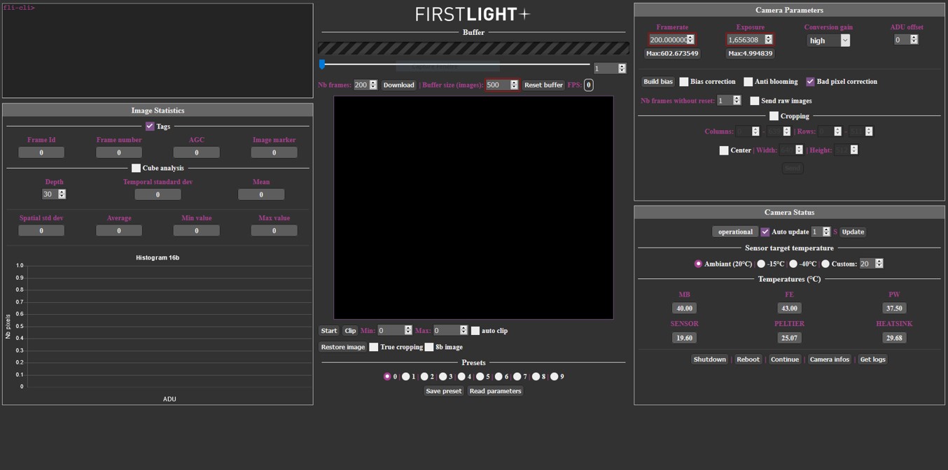
Figure 1 - HTTP GUI overview
The GUI consists of 5 panels:
The internal web server of the camera must be started before trying to connect to the camera with a web server. The HTTP server is started using the 'exec httpserver start' command. The console of the camera can be accessed using FirstLightVision or using putty application (COM or SSH connection).
Once started, the embedded web server will listen on the TCP port 8888 and can be accessed using the URL http://xxx.yyy.zzz.tttt:8888 in the web browser, where xxx.yyy.zzz.tttt stands for the IP address of the camera.
Note that the IP address of the camera can be retrieved using the 'ipaddress' command.
During the connection, a login/password prompt is displayed. The login is always adminnc, the default password is flicred1. The default password may have been changed on the camera and can be retrieve on the camera console using the password command.
Once connected, the web browser will show the same page as Figure 1.
Please note: Using FliVision, a button is directly available to start the web server.
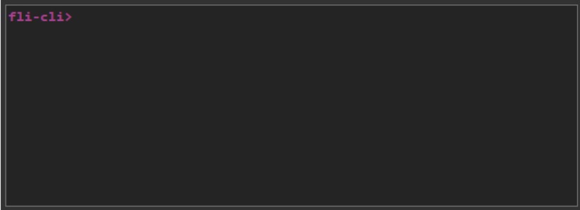
Figure 2 - Console module
The Console allows the user to send commands to the camera. When a command is sent, the user get the response and the GUI is updated. Below an example with the FPS command is provided:

Figure 3 - Console command example
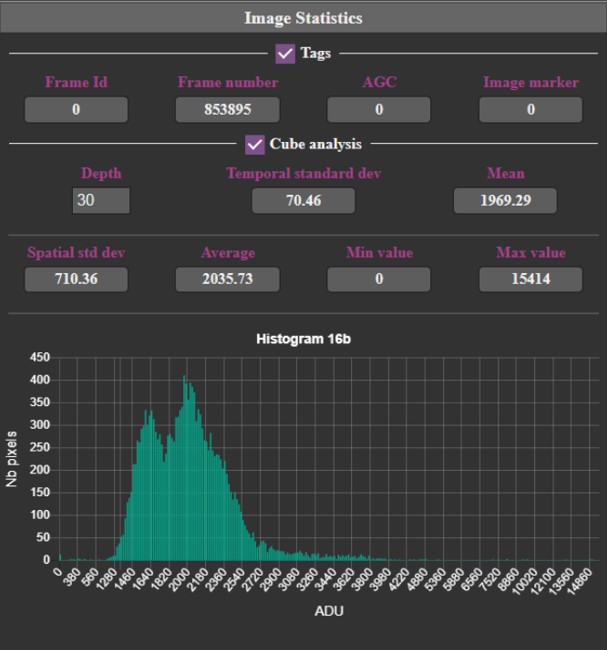
Figure 4 - Image statistics module
The Image Statistics module is made up of 4 parts which are refreshed every 200ms.
The Tags part displays information from the frame tags (first four pixels of the image), this feature can be enabled/disabled with the checkbox.
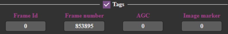
Figure 5 - Tags C-RED 2
The C-RED 2 tags are made up of five parts:
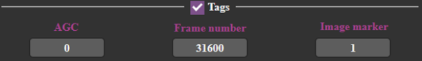 Figure 6 - Tags C-RED 3
C-RED 2 Lite / C-RED 3 tags are the identical to C-RED 2 / C-RED 2 ER tags, except for “Frame Id” that does not exist because of the absence of IMRO mode in C-RED 3 cameras.
The cube analysis part processes a cube of images with a default depth of 30 frames that can be changed by the user. It displays the temporal standard deviation and the Mean of the cube. The cube analysis can be enabled/disabled thanks to the checkbox, as it can slow the GUI and slow computers.
Spatial standard deviation, average, minimum and maximum values are always displayed and are computed with the current frame displayed.
The histogram displays the number of pixels for each value (-32768-32767) to have a repartition of the pixels in the image.
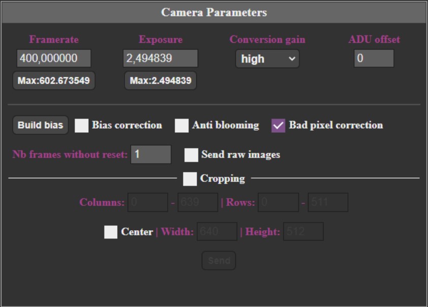
Figure 7 - Camera parameters C-RED 2 / C-RED 2 ER
The “Framerate” value corresponds to the number of frames per second sent by the camera.
Minimum frame rate is about 0.0001 fps. When acquiring full image size (640x512 pixels), the maximum frame rate is about 400 fps.
When the 600 FPS option has been acquired, the maximum frame rate is 602 fps.
Please note: in full frame sensor configuration, the Ethernet throughput of the camera does not allow to display more than about 25 frames per second. The extra frames sent by the camera are dropped.
Reducing image size (cropping) allows to achieve greater frame rates. The “Max” button allows to select the maximum frame rate according to the current camera configuration. The “Exposure” value allows to set the integration time of each frame.
Recommended minimum integration time is about 50 µs. For shorter integration times, please contact First Light Imaging at support@first-light.fr.
Maximum integration time depends on the framerate configured. It roughly corresponds to 1/frame rate.
The “Max” button allows to set the maximum integration time for a given framerate. Enable cropping allows to configure the camera to send a selected area of the sensor only. The area is selected through “Columns” and “Rows’ values or through “Width” and “Height” when “Center” is enabled.
The camera sensor requires the selected area to be aligned horizontally on 32 columns boundaries and vertically on 4 rows boundaries. The selected area width must also be a multiple of 32 columns, and height must be a multiple of 4 rows.
Please note: Columns are numbered 0-639, rows are numbered 0-511.
When configured in NDR mode, cropping area cannot be smaller than 96*72 pixels on firmware 3.1.1 and above. On previous firmware versions, the cropping area could not be set to a value less than ¼ of the sensor full resolution. This limitation does not exist when embedded computation is disabled (raw mode).
Please note: Trying to set a lower area will be rejected by the camera.
The “Conversion gain” combo-box allows to switch between different integration capacitor capacities, allowing to adapt the camera sensibility to the signal to be observed. High sensibility corresponds to the minimum integration capacity, whereas low sensibility corresponds to the maximum integration capacity.
“Nb frames without reset” spin box allows to switch between standard readout mode, where the sensor is reset before each integration period, and a specific sensor readout mode, where several frames are acquired without resetting the sensor (known as Non-Destructive Readout mode). When set to 1, the standard readout mode is used. When set to n greater than 1, the sensor is reset every n frames.
“Anti-blooming” checkbox controls the anti-blooming option of the sensor.
“Bad pixel correction” controls on-the-fly bad pixel correction embedded in the camera.
“Bias correction” checkbox controls on-the-fly bias correction embedded in the camera.
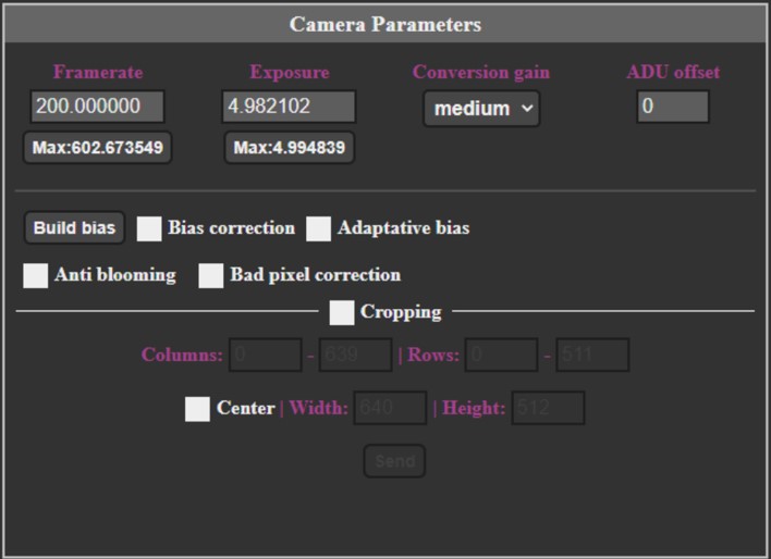
Figure 8 - Camera parameters C-RED 3
Same as C-RED 2 / C-RED 2 ER but without NDR.
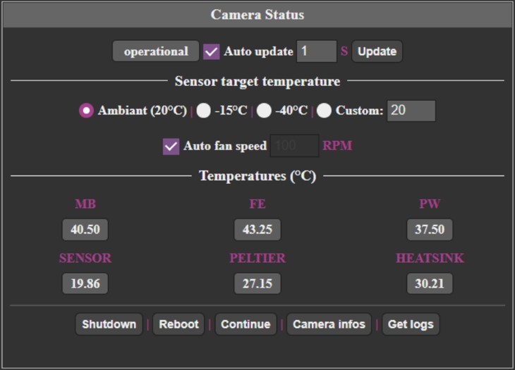
Figure 9 - Camera status C-RED 2 / C-RED 2 ER
This module is composed of 4 parts:
It also allows to enable/disable automatic fan speed and to set the speed in manual mode.
The “Continue” button is enabled when the camera is in safe mode.
It is recommended to shut down the camera before powering it down. The shutdown procedure is started by clicking the “Shutdown” button of the application. Once the shutdown procedure is initiated, wait a few seconds before powering it down. However, even if following the above shutdown process is highly recommended, a direct power off does not damage the camera. The potential consequences of a direct shut down are the loss of logs and a slightly longer startup time at the next boot.
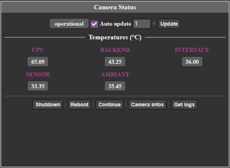
Figure 10 - Camera status C-RED 3
For C-RED 3 there is no cooling and no power measurement, only temperatures from camera are displayed.

Figure 11 - Central module
This part is common to all cameras:
A progress bar indicates the buffer filling, a slider and a spinbox are available to navigate in the buffer. You can download images from the buffer by settings “Nb frames” and click on “Download”. The size of the buffer can be modified with the spinbox “Buffer size (images)”. The button “Reset buffer” reset the buffer. The received speed is indicated next to “FPS”.
On the middle there is the image display, you can use left mouse click to do a clip and right mouse clip to do an analysis rectangle. With the mouse wheel you can zoom in/out and move the image Under the image display there are:
In the “Presets” section (only for C-RED 2/ER/3) you can save the parameters in a preset and load them. “Read parameters” button refresh all parameters of the GUI.

© Oxford Instruments 2026