Resources
 Part of the Oxford Instruments Group
Expand
Collapse
Part of the Oxford Instruments Group
Application Notes
Author: Andor
Published: 10 Feb 2021 · Last updated: 02 Mar 2022
Tags: tools-tomography
For higher X-ray energies >15 keV or ‘Hard’ X-rays standard direct detection methods such as Charged Coupled Devices (CCDs) are unable to effectively detect X-rays. Additionally, in the case of neutrons the damaging effects of neutron radiation would rapidly irreversibly damage both the camera and its electronics. The solution is to introduce a transducer or scintillator material into the system to convert the incident photons/neutrons into photons, which are then visible to the detector.
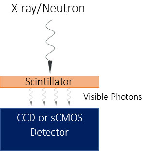
Figure 1: An illustration of a simplified indirect X-ray and neutron detection setup
Indirect detection involves two steps the first step involves a material, commonly a scintillator, to convert the incident X-ray photons into visible wavelength photons. The photons are then directly detected by the CCD in the second step. These 'converter' materials comprise of an extensive range of options of both phosphors and scintillators, selection depends on the specific requirement for detection, for example energy range, spatial resolution etc.
As shown in the sensor range diagram (Figure 1), indirect detection is the only option once the energies of X-ray photons is greater than >20 keV, as the CCD is no longer able to absorb the photons within the depletion zone. The requirement to convert the incident photon has some key disadvantages, primarily the actual conversion process is very inefficient. Also, as the incident photon is no longer directly detected there is no longer the ability to correlate the number of electrons to the incident energies. There has been a series of evolutions of design and in the components, which has improved the detection of signal.
Figure 2: Andor Webinar on Indirect X-ray Detection
Phosphor Sensor Coatings
The sensor is coated with a phosphor, for example Gadolinium Oxysulphide (Gd2O2S:Tb) often referred to as GADOX, also known as P43. The phosphor layer absorbs X-ray photons and emits visible photons predominately at 545 nm (2.28 eV), and has approximately a 15% conversion efficiency, i.e. 15% of the absorbed X-ray photon energy is converted into visible photons. However, only a fraction of generated photons will reach the detector as they are emitted in all directions. This illustrates the inefficiency of the conversion process with both signal and spatial resolution, as the secondary emission will effectively spread from the generation point. Increasing the depth of the scintillator, relates to the energy range that it will be able to absorb and convert, however the thicker it becomes, there is an equivalent reduction in the spatial resolution, so again a balance must be found.
Fiber Coupled Systems
Fibre optically coupled indirect detection systems couple a scintillator directly onto a fibre optically plate that is coupled back onto a sensor. This effectively maintains spatial resolution as it channels the light via the individual fibres onto the sensor, reducing the spread of the light from the generation point. The introduction of the fiber-optic has other important advantages, the fiber can be extruded to form a taper, this increases the area that can be imaged, albeit with a demagnification of the image. It can also offer protection to the sensor from the harder X-rays, which are in themselves damaging to the silicon structure of the CCD. Additionally, fibre coupled systems offer a significantly higher light throughput than lens coupled systems. Andor technology offers several fibre optically coupled camera solutions complete with scintillators and beryllium filters as required.
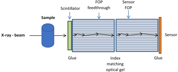
Figure 3: An example of a fibre optically coupled scintillator to sensor setup
Lens Coupled Systems
There has been a growing interest in the use of lens-based camera systems to image scintillator screens. The method is popular as the active area of the scintillator can be very large, 50 cm2 and larger. Moreover, the camera is protected from the direct path of the damaging hard X-ray, even neutron and gamma sources can be used in this method. From a camera position this is also a simpler and easier method as there is no need to modify or change the standard camera which allows for a quick and easy replacement or upgrade. See below an example of lens coupled camera setups the first depicting a simple linear setup and the second a common neutron/X-ray imaging setup in which the camera is positioned perpendicular to the incident beam.
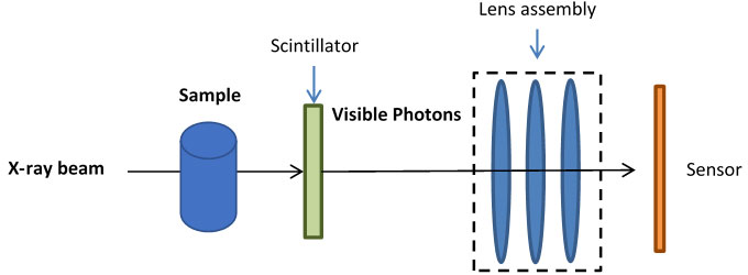
Figure 4: An example of a simple lens coupled scintillator to sensor setup
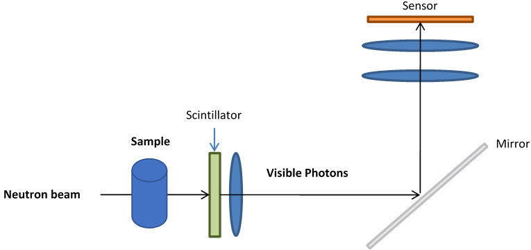
Figure 5: An example of a lens coupled scintillator to sensor setup in which the camera is perpendicular to the X-ray/neutron beam to protect it from damage.
Each of the sensor versions discussed have their associated advantages and disadvantages, however some simple rules can be applied:
There are further variations on these basic types of indirect detection. At Andor we have cameras ideally suited to the direct and indirect detection of X-rays and Neutrons and we use a dedicated team to design and build these bespoke systems. The design process looks at the requirements and matches the variety of components options, such as fiber and scintillator, to produce a final quality Andor product. Contact your local sales representative for more information.

© Oxford Instruments 2026
