Resources
 Part of the Oxford Instruments Group
Expand
Collapse
Part of the Oxford Instruments Group
Tutorials
Author: Andor Support Team
Published: 01 Apr 2022 · Last updated: 13 Apr 2022
Tags: support-resource
Spectra appear offset (shifted) from where the peak is expected. Generally, this can happen after re-attaching a camera or changing the grating turret. When this happens, the wavelength drive requires re- calibration using the following method.
The Offset Adjustment Control (Figure 1) allows the user to adjust the position of the wavelength motor drive to correct for any shift in the spectra. Detector or grating offset adjustment is selected via the tabs on the Offset Adjustment Control (this can be added to the Shamrock panel from Display >> Offset Adjustment).
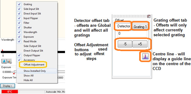
Figure 1: Detector and grating offset adjustment control.
The Detector offset value can be adjusted to correct for any mechanical change that shifts (offsets) the displayed spectrum from the expected calibrated position. For example, if a camera is removed and refitted, or a grating turret is removed and refitted there will most likely be a small mechanical change in the exact re-positioning of the component. Any Detector offset introduced will be ‘global’, i.e., any offset will be independent of the grating being used and will apply to all gratings.
The Grating offset values are used to correct for any shift between the displayed spectra from the expected calibrated position and will only apply to the currently selected grating. The grating offsets are normally only adjusted when a new grating turret is installed or upon initial setup.
The following describes the procedure for the detector offset adjustment, but the grating offset adjustments are performed in the same manner.
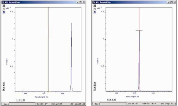
Figure 2: Spectra acquired before (left) & after (right) Detector Offset Adjustment
When complete, the Shamrock EEPROM is automatically updated with the new Offset values and will be applied each time the spectrograph powers on.

© Oxford Instruments 2026
