Resources
 Part of the Oxford Instruments Group
Expand
Collapse
 Part of the Oxford Instruments Group
The unique combination of high acquisition speeds, high sensitivity and high dynamic range of Scientific CMOS (sCMOS) technology has proven extremely attractive for applications ranging from Astronomy to Cold Atom studies, Flow Mechanics (e.g. Particle Image Velocimetry) or Cell Microscopy. Coupled to fast-gated image intensifier technology, it enables fast, high dynamic range, nanosecond (ns) time-resolved studies of Plasma or Flow/Spray/Flame dynamics. This technical note presents a new set of dedicated, on-head Spectroscopy modes for intelligent and seamless spectral and multi-track data acquisition available on Andor’s ZL41 Wave sCMOS and ns time-resolved iStar sCMOS platforms.
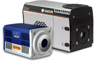
Figure 1 - Example of micro-spectroscopy setup with a ZL41 Wave 5.5 sCMOS and Kymera 193i spectrograph for fast luminescence kinetics studies of nano-materials or biological samples
Asymmetric Binning
Users can configure any combination of vertical and horizontal binning on the sCMOS sensor for a given region of interest (ROI). On-head processing provides ready-to-analyse binned single spectrum or multiple (multi-track) spectra prior to transmission through the 10-tap or USB3 interface. This convenient, upfront data management greatly reduces the data set size to be handled and processed by users through the acquisition software (see figure 2).

Figure 2 – (Left) Solis software user interface for spectroscopy with ZL41 Wave / iStar sCMOS and Kymera/Shamrock spectrographs real-time controls (showing a ‘step-and-glue’ spectrum of a Hg-Ar source). (Right) Andor Solis asymmetric (Spectroscopy) binning user interface.
In Solis Binning/ROI tab, users can independently set the channel (ROI) height where the spectrum is imaged on the sensor (a), the vertical binning (b) and horizontal (c) binning parameters best matching the experimental resolution. ROI height and vertical binning should be set to the same value.
Note: To access the best spectral rates summarised in table 1, signal should be centred vertically on the sensor and Auto Vertical Centring option ticked in Solis software interface (d).
| Array size (Width x Height) | Zl41 Wave 5.5 10-tap / USB3.0 | ZL41 Wave 4.2 10-tap / USB3.0 Rolling Shutter (overlap ON) | iStar sCMOS USB3.0 Global Shutter (overlap OFF) | |
| Rolling Shutter (overlap ON) | Global Shutter (overlap OFF) | |||
| any x 8 | 27,057 | 4,008 | 26,041 | 4,008 |
| any x 12 | 18,038 | 3,491 | 17,361 | 3,491 |
| any x 16 | 13,528 | 3,092 | 13,020 | 3,092 |
| any x 128 | 1,691 | 736 | 1,627 | 736 |
| any x 512 | 422 | 203 | 406 | 203 |
| any x 1040 | 208 | 102 | 200 | 102 |
| any x 2048 | 105 | 52 | 101 | 52 |
Table 1 – Spectral rates (sps) achievable with ZL41 Wave 5.5 & 4.2 and iStar sCMOS for selected vertically-binned ROIs
Extended bit-depth mode
This mode is recommended for Spectroscopy or Imaging experiments using extensive pixel binning.
Standard pixel encoding settings on the ZL41 Wave and iStar sCMOS are 12-bit (low noise or high well capacity) or 16-bit (low noise and high well capacity), which are designed to preserve dynamic range for 1x1 pixel binning. The ‘standard’ maximum digital value transmitted through the camera interface is therefore limited to 16-bit.
In the case of multiple pixel binning where the sum of the counts exceeds 16-bit, signal will be digitally ‘capped’ at 16-bit and will therefore result in a loss of quantitative information for the brightest components of the incoming signal on the detector.
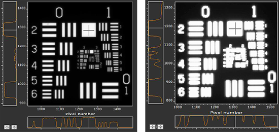
Figure 3 – Image of USAF target taken with ZL41 Wave 5.5 in 1x1 (left) and 4x4 pixel binning (right) scenarios with ‘standard’ data transfer mode
Referring to figure 3, an un-binned image of a USAF target taken with the ZL41 Wave is shown on the left. The individual pixel intensity at the crosshair in the largest white square on the image is ~40,000 counts (<16-bit). The image on the right is taken in the same conditions but with 4x4 pixel binning, with a ‘theoretical’ super-pixel count level at the crosshair of 16 x 40,000 counts ~640,000 counts (19-20 bit).
The standard transfer protocol of the ZL41 Wave and iStar sCMOS only allows the transmission of the lower 16-bit information, resulting in artificially saturated super-pixel at 16-bit.
Figure 4 shows the same 4x4 pixel binned images with ‘standard’ 16-bit data transfer (left) and extended bit depth mode enabled (right). The full 640,000 counts (19-20 bit) data can now be transferred to the computer with the full data dynamic range therefore preserved.
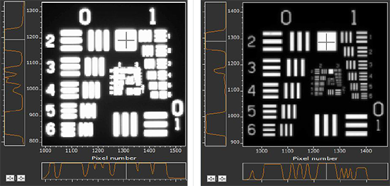
Figure 4 – Image of USAF target taken with ZL41 Wave 5.5 in 4x4 pixel binning scenario with ‘standard’ data transfer mode limited to 16-bit data size (left) and extended bit depth mode enabled (right)
Note: Extended dynamic range mode (32-bit data transmission) is automatically enabled in Andor Solis software when user selects ‘a’ binning mode. The activation of this mode may result in slower acquisition rates due to the increased size of the data packets. This option can be manually disabled if the dynamic range of the super-pixel (resulting from multiple pixel binning) is lower than 16-bit, allowing access to the fastest spectral or imaging acquisition rates.
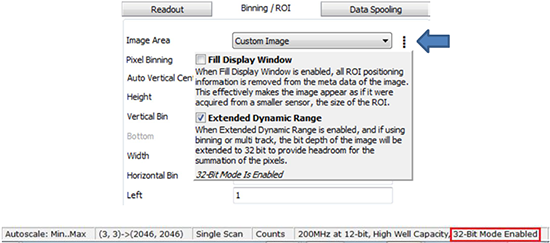
Figure 5 – Extended dynamic range mode user interface in Andor Solis software. Activation status of this mode is indicated at the bottom of the Solis window.
Multi-track mode
In scenarios where multiple spectra must be acquired simultaneously on the detector (e.g. multi-way fibre optic bundle), users can create one or more individual acquisition tracks that can be defined (in rows) by their height and vertical position. The position of the tracks can be adjusted to match the light pattern produced on the sensor.
Only the sections of the sCMOS image chip that are selected in multi-track mode are transmitted across to the computer. All the selected tracks are transmitted as a single frame for each acquisition. Users can define up to 256 individual areas of any height. Each track can be individually set up to have either 1x1 binning or be full vertically binned. Users cannot define the width of the tracks, whether individually or globally – the tracks width is equal to the full width of the sensor. Figure 6 shows multi-track setup interface in Andor Solis software.
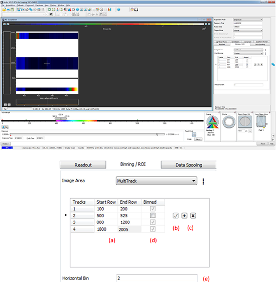
Figure 6 – Multi-track interface in Solis software
In Solis Binning/ROI tab, under MultiTrack image area option, users can define the start and end row of each individual track (a); track parameters must be validated to be taken in account (b). Tracks can be easily added / deleted (c), and users can choose whether individual tracks must be vertically binned (d), and if horizontal binning should be applied (e).
Note: The total ROI height and position will be determined by the start position of Track 1 and end position of track N where N is the number of tracks. The fastest acquisition rates shown on table 2 will be obtained when the multi-track pattern is centred vertically on the sensor.
| Number of tracks (centred vertically) | Track height (h, pixels) | Tracks separation (d, pixels) | ZL41 Wave 5.5 10-tap / USB3.0 | ZL41 Wave 4.2 Plus 10-tap / USB3.0 Rolling Shutter (overlap ON) | iStar sCMOS USB3.0 Global Shutter (overlap OFF) | |
| Rolling Shutter (overlap ON) | Global Shutter (overlap OFF) | |||||
| 2 | 12 | 12 | 6,012 | 1,967 | 5,787 | 1,967 |
| 2 | 20 | 20 | 3,607 | 1,370 | 3,472 | 1,370 |
| 2 | 154 | 77 | 557 | 265 | 536 | 265 |
| 20 | 12 | 12 | 462 | 222 | 445 | 222 |
| 20 | 20 | 20 | 277 | 135 | 267 | 135 |
| 50 | 12 | 12 | 182 | 89 | 175 | 89 |
| 50 | 20 | 20 | 109 | 54 | 105 | 54 |
| 256 | 8 | 0 | 105 | 52 | 101 | 52 |
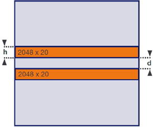
Table 2 – Acquisition rates (multi-track set/second) achievable with ZL41 Wave 5.5 & 4.2, iStar sCMOS for selected track pattern configurations
