Published: 01 Dec 2023 · Last updated: 27 Jun 2024
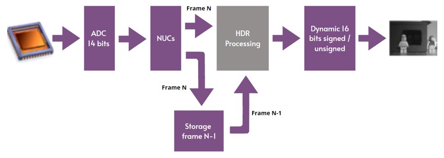
The purpose of this technical note is to explain the operation of the HDR mode on a C-RED 2 / C-RED 3 camera. Main blocs of HDR will be explained, the mode will be described step by step. The last part exposes the limitations/restrictions.
Theory of Operation
Sensor
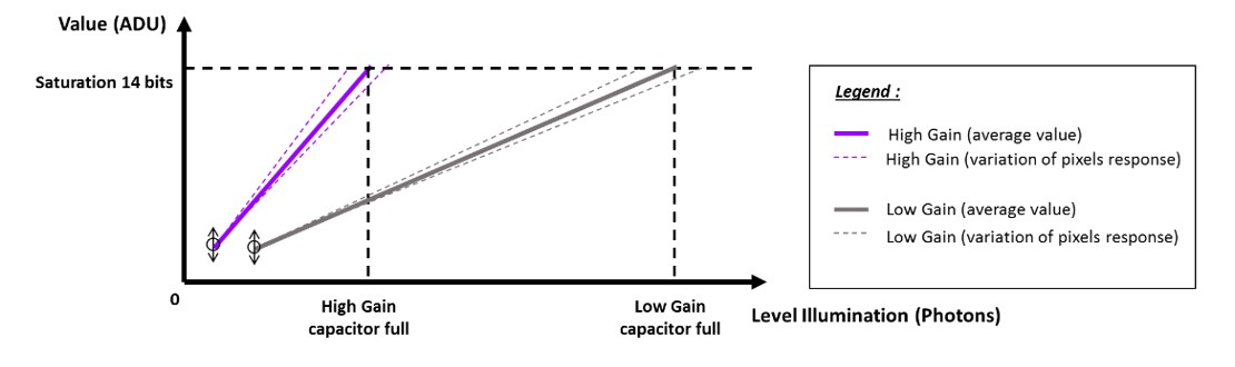
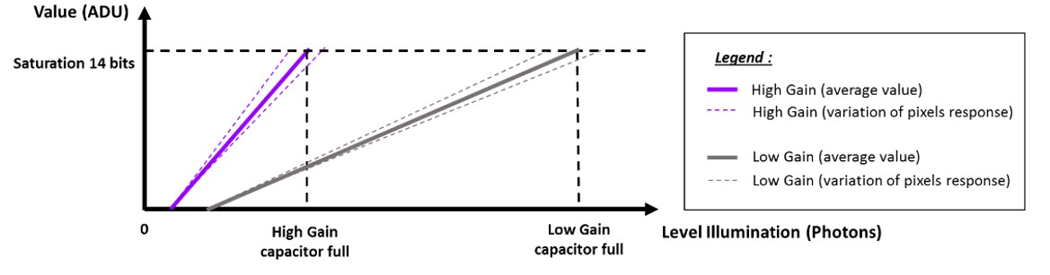
C-RED 2 / C-RED 3 uses the Sofradir SNAKE sensor to acquire frames. In the sensor, different integration capacitors are available. The camera uses successively images from two capacitors:
High Gain capacitor which can store 43Ke- with a noise around 30e-
Low Gain capacitor which can store 1.44Me-
There are many advantages to combine images from two different capacitors in the same frame:
For low light illuminated areas, the camera uses pixels from HG capacitor with lowest noise.
For high illuminated zones, the camera uses pixels from LG frame with the highest storage capacity.
The switching of the capacitor used in the sensor is automatically done by the firmware. The capacity of the low gain capacitor compared to the 30e- readout noise of high gain capacitor allows a 93.6 dB dynamic in the same frame.
Analog to Digital Conversion
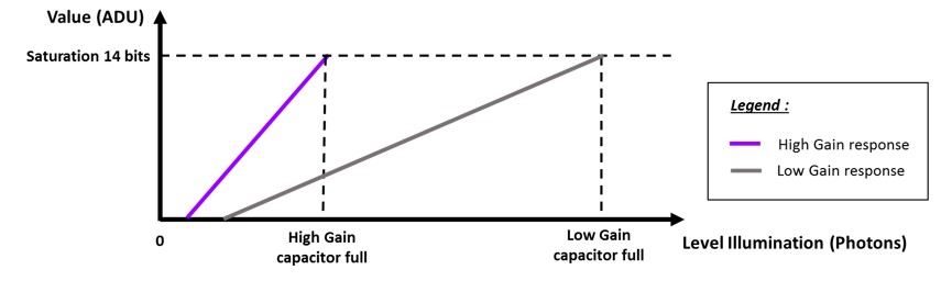
Pixels are digitalized in 14 bits unsigned format. For each capacitor, the pixel value in ADU is a function of level illumination in photons. The dynamic range in ADU is the same for Low and High Gain capacitors. Dynamic useful ranges in photons are not the same for the HG and LG capacitors.
Raw light integration evolution for the 2 capacities.
Because of the sensor architecture, the light integration is linear. Below saturation level, it is almost a straight line.
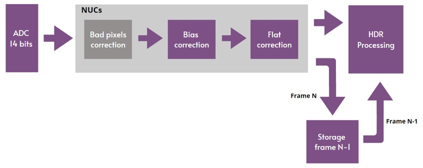
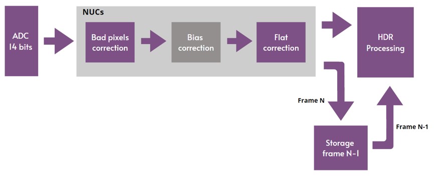
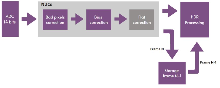
Non-uniformity corrections
Three different corrections can be made directly by the camera. The camera applies automatically the good correction depending on the frame sent by the sensor: HG or LG.
Bad Pixel correction
When applied, bad pixels are replaced. This correction can be applied or not by the user.
Bias Correction
The bias correction subtracts the dark frame from the image sent by the sensor. For HDR mode, it is mandatory to compute a bias correction for each capacitor.
This operation can be done automatically by the camera. After bias correction, images from each capacitor have the same ADU reference which is around 0 ADU in no light conditions.
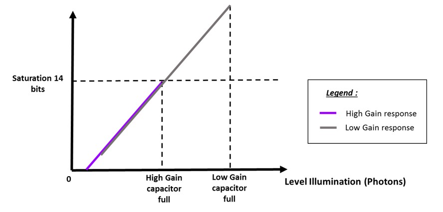
Light integration evolution after bias correction.
Flat Correction
Flat correction fixes the non-uniformity response of the pixels. When applying this correction, all the pixels have the same response for the same illumination. For HDR mode, this correction improves the HDR image at the output of the camera. This correction is however optional.
Light integration evolution after bias and flat correction.
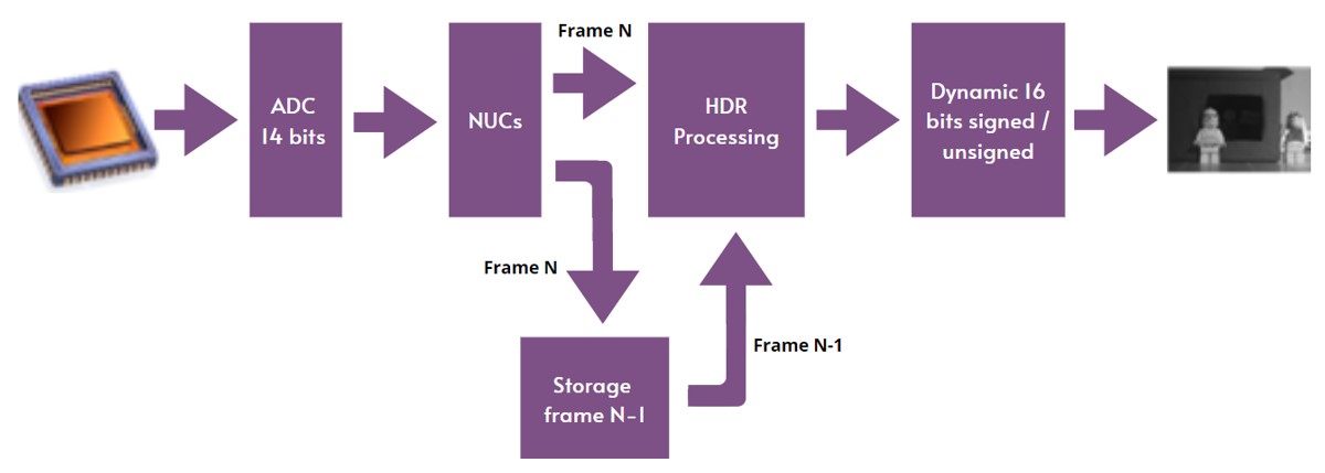
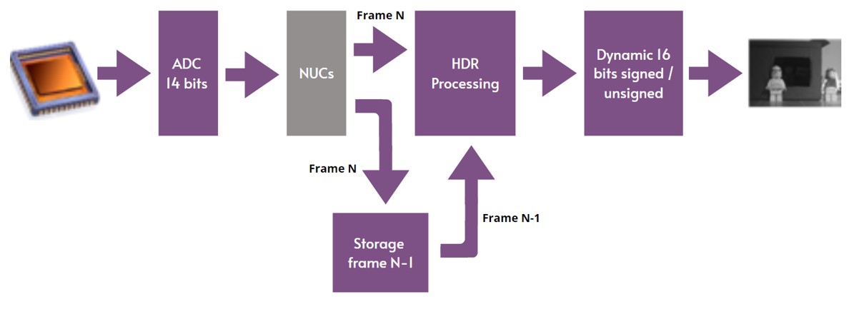
HDR Processing
After NUCs correction, the pixels are sent to the HDR Processing bloc. the HDR processing bloc maps the adapts the dynamic of the LG capacitor on HG capacitor. For a range of level illumination, HG and LG capacitors give the same response. There is a covering between the two capacitors.
Light integration evolution after bias, flat, LG gain and LG offset correction.
Output Dynamic
Two output pixels options are available in the camera:
HDR mode : 16 bits signed pixel format
HDR mode extended : 16 bits unsigned pixel format
The “HDR mode extended” allows to have the maximum dynamic range of 93.6dB. This dynamic is reduced for “HDR mode” at 87.6dB. Compared to “HDR extended mode”, the pixel value is right shifted, the least significant bit is lost.
Please Note:
Before this bloc, pixels use full precision (24 bits in the FPGA)
HDR System Gain
The HDR system gain is different from the CDS system gain. The table 1 gives the multiplier factor to use to find the HDR system gain depending on:
Table 2: HDR system gain with CDS system gain equal to 2.3 e-/ADU
Restrictions/Limitations
Integration While Read Mode
To run the camera at full speed (400 or 600 FPS with C-RED 2, or 600 FPS with C-RED 3) the sensor IWR mode must be used. In this mode, the integration of the frame N+1 begins while the sensor outputs the frame N.
Non Linearity of Low Gain Capacitor Response
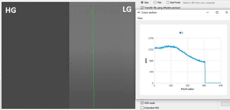
Unfortunately, in this mode, a small spatial non uniformity is present on the low gain capacity. This spatial non uniformity depends on illumination level and is mainly present in the transition area between high and low gain. This phenomenon can be seen easily in front of a flat field. However, because this effect occurs mainly in the transition area where a mix of the two images is used, with normal image (not a flat field), this effect is not very visible.
The form of the distortion is a wave that appears first at the bottom of a LG capacitor frame for low illuminations levels and that moves up when the light illumination is augmented. For light level illuminations more important, the deformation is not visible.
Please Note:
It is difficult on real conditions to see this deformation.
This phenomenon does not exist in ITR mode.
High Motion Scene
To build an HDR image, one low gain and one high gain images are used. Each image is used two times, this is why the max framerate is still 400 or 600 fps (with 600.fps license). However, the true speed rate for HG and LG frames is divided by two, 200 FPS or 300 FPS (with 600 fps license). Also, the HDR frame mixer uses only the HG pixel values to determine the value of the output pixels.
For these reasons, a quick motion in the scene can cause slight ghost areas to appear at transition zones between LG and HG pixels. However, the averaging of the pixels in the transition zone between LG and HG slightly blurs this area and attenuates this ghost effect.