Resources
 Part of the Oxford Instruments Group
Expand
Collapse
 Part of the Oxford Instruments Group
Dark Current - The charge accumulated within a well, in the absence of light. Also the background current that flows in a charge-coupled device or image intensifier of a camera system. Cooling the photodetector's primary imaging surface (i.e., the CCD's photoconductor or the image intensifier's photocathode) can reduce or eliminate dark current.
Dark Noise - The statistical variation of the dark current, equal to the square root of the dark current. Dark current can be subtracted from an image, while dark noise remains.
Dark Signal - Dark signal, a charge usually expressed as a number of electrons, is produced by the flow of dark current during the exposure time. All CCDs produce a dark current, an actual current that is measurable in (typically tenths of) milliamps per pixel. The dark signal adds to your measured signal level, and increases the amount of noise in the measured signal.Since the dark signal varies with temperature, it can cause background values to increase over time. It also sets a limit on the useful exposure time. Reducing the temperature of the CCD reduces dark signal (typically, for every 7°C that temperature falls, dark signal halves). CCD readout noise is low, and so as not to compromise this by shot noise from the dark signal, it is important to cool the detector to reduce the dark signal. If you are using an exposure time of less than a few seconds, cooling the detector below 0°C will generally remove most of the shot noise caused by dark signal.
Deep-Depletion CCD - A CCD that has been designed to provide enhanced near-infrared and high-energy X-ray sensitivity. These devices utilize a bias voltage applied to a thick layer of high-resistivity silicon in order to produce a deeper depletion region (active photosensitive area) than that of conventional CCDs. This architecture allows longer-wavelength photons to interact within the layer as opposed to merely penetrate it.
Detection Limit - The Detection Limit is a measure of the smallest signal that can be detected in a single readout. The smallest signal is defined as the signal whose level is equal to the noise accompanying that signal, i.e. a signal to noise ratio (S/N) of unity. Sources of noise are:
If the signal is small, we can ignore its shot noise. Furthermore, if a suitably low operating temperature and short exposure time can be achieved, the lowest detection limit will equal the readout noise.
Diffraction Grating - An optical device used to disperse light into a spectrum. It is ruled with closely-spaced (typically several thousand per cm) fine parallel grooves that produce interference patterns in a way that separates all the components of the incoming light. A diffraction grating can be used as the main dispersing element in a spectrograph. The diffraction pattern produced by the grating is described by the equation:m (?) = d sin (?), where:4.0 m is the order number
? is a selected wavelength
d is the spacing of the grooves
? is the angle of incidence of light
A transmission grating has grooves ruled onto a transparent material, such as glass or Perspex, so that a beam of light passed through the grating is partly split into sets, or orders, with spectra on either side of it; the blue light is diffracted the least and the red light the most in each order. The orders of spectra increase in dispersion and faintness with distance from the direct beam. A reflection grating has grooves ruled onto a reflective coating on a surface that may be plane or concave, the latter being able to focus light. Its advantage over a transmission grating is that it produces a spectrum extending from ultraviolet to infrared, since the light doesn't pass through the grating material.
Digital - A scheme for representing data via quantized, discrete steps.
Digitize - To convert data (or images) into a digital format.
Dynamic Range - The ratio of the maximum (brightest) to minimum (darkest) signal levels present in an image. For instance, a true 12-bit digital camera is capable of providing a dynamic range of 4096:1.
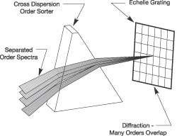
Echelle Grating - A diffraction grating in which the grooves are quite widely spaced and have a zigzag or step-like cross-sectional profile. The name is French for ladder. The light to be dispersed is made to fall on the grating at right angles to the faces of the grooves. This has the effect of producing a series of overlapping spectra with a high degree of resolution. A second, low-dispersion grating, or a prism, arranged perpendicular to the èchelle, serves to separate out the overlapping spectra.
EM Radiation - Electromagnetic Waves are produced by the motion of electrically charged particles. These waves are also called Electromagnetic Radiation because they radiate from the electrically charged particles. They travel through empty space as well as through air and other substances. Electromagnetic radiation can be defined by wavelength, frequency, energy, e.g.:
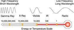
By measuring one of the characteristics of radiation, we can determine the other, i.e.: Frequency = Speed of light / wavelength (?)
Energy = Constant x Frequency (f)
E = mc2
EM Spectrum - As Electromagnetic Radiation is spread across many wavelengths, the term Electromagnetic Spectrum is used to describe the wavelength areas. This includes radio waves, microwaves, infrared, visible light, ultraviolet, x rays, gamma rays, and other electromagnetic radiation of long and short wavelengths. As you can see from the figure below (which shows the approximate wavelengths, frequencies, and energies for selected regions of the electromagnetic spectrum) there is, for example, no definitive boundary between where Radio Waves change to Microwaves. Rather, the various portions of the spectrum blend into one another, i.e.:
Wavelength (and its dependent properties, frequency and energy) is the fundamental differentiator between any type of electromagnetic radiation, whether it be long wavelength Radio Waves or short wavelength X-Rays.
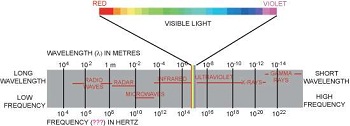
If all electromagnetic radiation is fundamentally the same thing, you might ask, "Why don't we see radio waves like we see light?" or "Why do we need special infrared light bulbs to heat things up?" Although all portions of the electromagnetic spectrum are governed by the same laws, their different wavelengths and different energies allow them to have different effects on matter. Radio waves, for example, have such a long wave length and low energy that our eyes can't detect them and they pass through our bodies. It takes a metal antenna with special electronics to capture and amplify radio waves. Infrared radiation is made up of wavelengths that are easily absorbed by matter and turned into heat. X-rays are radiation of wavelengths that can pass through soft tissue but are stopped by bone.
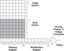
EMCCD Camera - Advances in sensor technology have led to the development on a new generation of ultra-sensitive, low light CCDs.At the heart of your detector is the latest Electron Multiplying Charged Coupled Device (EMCCD), a revolutionary technology, capable of single photon detection.An EMCCD, is a silicon-based semiconductor chip bearing a two-dimensional matrix of photo-sensors, or pixels. This matrix is usually referred to as the image area. The pixels are often described as being arranged in rows and columns - the rows running horizontally and the columns vertically. The EMCCD in the iXonEM+ detector is identical in structure to a conventional CCD but with the shift register extended to include an additional section, the Gain Register.
Etaloning - In a standard back-illuminated CCD, reflections between the parallel front and back surfaces of the device that lead to unwanted fringes of constructive and destructive interference. This resonant effect causes the device to become semi-transparent in the near-infrared region of the spectrum.
Exposure Time - The length of time that a CCD is accumulating charge.
Faceplate - In a CCD camera system, the front surface of the camera head, which often incorporates a window. The faceplate is sometimes used to support a target, or mount the camera head.
Fiberoptic-Coupled (Bonded) CCD - A CCD with a coherent fiberoptic bundle bonded to the CCD's imaging surface. The fibreoptic bundle is used to transfer an image source to the imaging surface of the CCD.
Fiberoptic - Fiberoptics, also referred to as optical fiber, refers to the medium and the technology, which is used in the transmission of information in the form of light pulses through very fine, flexible glass or plastic fibers (which are usually about 120µm diameter).
Fill Factor - A term that relates to the light-gathering area of a CCD. For instance, a CCD with 90% fill factor has an imaging array in which 10% of each pixel's area is insensitive to light.
F-Mount - A standard lens mount common to many scientific instruments. (Back focal length: 46.5 mm.)
Fps - Frames per second.
Frame - One image moved from a CCD in a full parallel shift.
Frame Buffer - In a digital imaging system, the hardware in which the frame memory (RAM that stores full frames of the image signal) resides.
Frame-Transfer CCD - A type of CCD used for quantitative electronic imaging. Frame-transfer CCDs divide the parallel register into two areas (arrays): an image array (for image collection) and a storage array (for image storage). After the image array is exposed to light, the electronic image is shifted to the storage array and read out. A frame-transfer CCD can operate without a shutter, running continuously at high rates.
Front-Illuminated CCD - A CCD in which the gate structure is located in front of the potential wells.
Full-Frame CCD - The simplest type of CCD. Full-frame CCDs use the entire active parallel register to expose photons and to integrate and transport charge. They utilize a shutter to control the exposure and block light during CCD readout, preventing charge smearing.
Full Well Capacity - The number of electrons that can be held in one potential well. It is assumed that all pixels on a CCD have the same well size and that each well can hold the same number of electrons.
Gain & Dynamic Range - As the gain is increased it will at some point begin to cause a decrease in Dynamic Range. This occurs when the gain equals the readout noise, in electrons. Therefore at 1MHz readout rates the Dynamic Range will be maintained at over 20,000:1 for gains up to about 20 times, while at 62.5kHz it will be maintained at over 43,000:1 for gains up to 6 times. If higher sensitivities (and hence higher gains) are required then there will have to be a trade off for Dynamic Range. To maintain as much Dynamic Range as possible it is advisable not to use a higher gain than is necessary to measure a signal.
Gain & Noise - The output from the gain register is fed into a conventional CCD output amplifier. This amplifier, even in a scientific CCD, will have a readout noise of a few electrons rms and around 10 or 20 electrons rms at MHz readout rates. However this noise will effectively be reduced by the multiplication factor of the gain register which, when high enough, will achieve noise levels below 1 electron rms. So by using the gain you can effectively reduce the noise to insignificant levels at any readout speed.For example, the iXonEM+ 87 has an s readout noise of a few to tens of electrons, depending on read out speed.Using gain will itself add some noise to a measured signal due to the statistical nature of the multiplication process. A similar effect exists in ICCDs and is referred to as the Noise Factor. The amount added is dependent on the signal level and the gain.If there is no gain, then there is no extra noise.At high gain (tens of times higher) it is calculated as the square root of N (where N is the signal in electrons). This will add to the shot noise of the signal to become the square root of 2N.So if the signal is large enough to be above the readout noise then there is probably no need for gain and it should be reduced or turned off. Conversely, if the signal is being lost in the readout noise then increasing the gain is the only way to detect it. If the gain is set high enough, then detection of single electron events will be possible. These events will appear on an image as a spike several hundred counts high. In Andor EMCCD cameras the gain is limited to a maximum of 255 times at -50ºC for standard systems. This is comparable to high end ICCDs.
Gain Register - In an EMCCD, a gain register is placed between the shift register and the output amplifier .The electrons are multiplied in the gain register by impact ionisation.
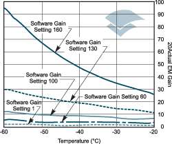
Gain Temperature dependence - The gain of an EMCCD system varies with temperature. The graph below shows how the gain multiplication increases as the temperature decreases. Curves are shown for various software gain settings and the figures are typical values. So if a system is operated at room temperature it will have reduced gain. Because of this temperature dependence it is recommended that the system is cooled, so that the temperature, and hence the gain, is stabilized.
So if a system is operated at room temperature it will have reduced gain. Because of this temperature dependence it is recommended that the system is cooled, so that the temperature, and hence the gain, is stabilized.
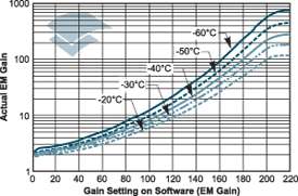
The graph below shows how the EM Gain setting on the software is related to the actual electron multiplication factor for various temperature settings (again the figures are typical):
Gate Structure - In a traditional CCD, the polysilicon structure located on the parallel register. Polysilicon gates are transparent at long wavelengths, but become opaque at wavelengths shorter than 400 nm.
Gating - In an ICCD camera system, the application of a voltage that switches the image intensifier on and off in very short intervals. Gating improves temporal resolution.
Gray Level - The brightness of a pixel in an image, expressed as an integer. Gray levels range from 0 (black) to 255 (white) for an 8-bit digital signal, and from 0 (black) to 4095 (white) for a 12-bit digital signal.
HCCD Camera - High-performance CCD camera. A CCD-based digital imaging system that utilizes advanced design features, such as low-noise electronics and cooled-detector technology, to optimize camera capabilities for scientific or industrial imaging applications.
High-Speed Framing - The process by which frames are read from a CCD at a rapid rate.
Host Computer - The primary or controlling computer for a digital camera.
ICCD Camera - Intensified CCD camera. A digital imaging (or spectroscopy) system that utilizes an image intensifier coupled to a CCD. These cameras offer high sensitivity in ultra-low-light-level conditions. Gating can be utilized to provide better temporal resolution.
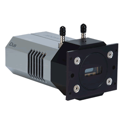
iDus - Andor's USB CCD camera for Spectroscopy.For full specifications of the iDus, please refer to the Products section.
Image Array - The portion of a frame-transfer CCD that is exposed to light (and in which the image is collected). After the CCD is exposed, charge is shifted to the other half of the device, the storage array.
Image Averaging - A method of reducing random image noise by averaging a pixel's brightness throughout a series of successive frames.
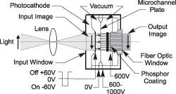
Image Intensifier - An Image Intensifier is a device that amplifies the intensity of an image, not the size of the image.The device is small, typically 1 to 2 inches in diameter by about 1 inch thick. An image is projected on to the input window of the device and an intensified image appears on its exit window (usually a fiber optic plate). As well as amplifying, an image intensifier can rapidly be switched on and off, allowing it to be used as a very fast shutter.The image intensifier used in the system can be either a 2nd Generation (GEN II) or a 3rd Generation (GEN III) tube. This is a proximity-focused device that is compact and, more importantly, is easily gated to 2 ns time-scales.There are three major elements in an image intensifier which determine the performance of the device and they are as follows:
The Photocathode
The Microchannel Plate (MCP)
The output Phosphor Screen
Indium Gallium Arsenide (InGaAs) - A material used in some detectors (e.g., PDAs) to provide higher QE in the near-infrared region of the spectrum.
Indium Tin Oxide - Indium tin oxide. A material used in some CCD gates to provide higher QE, particularly in the blue-green region of the spectrum.
Infrared (IR) - The region beyond the visible spectrum at the red end, typically greater than 770 nm.
Integration - The act of accumulating signal or charge on a CCD.
Interline Mask - Opaque strips that span an interline-transfer CCD and function as storage areas.
Interline-Transfer CCD - A type of CCD in which the parallel register is subdivided so that opaque strips span and mask the columns of pixels. The masks act as storage areas. When the CCD is exposed to light, the image accumulates in the exposed areas (photosites) of the parallel register. In the serial register, the entire image is under the interline mask when it shifts for CCD readout. It is possible to shift the integrated charge quickly (200 ns) under the storage areas.
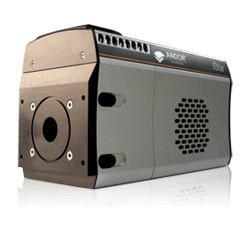
iStar - Andor's ICCD camera for low-light spectroscopy applications requiring fast gating.For full specifications of the iStar, please refer to the Products section.
iXonEM+ - Andor's first commercially available, revolutionary EMCCD camera for ultra sensitive dynamic digital imaging.For full specifications of the iXonEM+, please refer to the Products section.
