Resources
 Part of the Oxford Instruments Group
Expand
Collapse
Part of the Oxford Instruments Group
Technical Article
Author: Andor
Published: 10 Feb 2021 · Last updated: 11 Sep 2025
In order to efficiently detect photons with energy in the vacuum and extreme ultraviolet and soft and hard x-ray range, an environment free of particles that could interfere with the useful photon signal is generally created between the high energy radiation source and the detector. This is achieved by pumping out of the experimental chamber the atomic or molecular species that would absorb the useful radiation and be ionised, hence creating ‘pollutant’ species.
Here we highlight the key vacuum flange interfaces available for connecting Andor CCD detectors to vacuum chambers or spectrographs for a range of applications including x-ray plasma diagnostics, extreme ultraviolet (EUV/XUV) imaging & microscopy, x-ray diffraction imaging or spectroscopy, or high harmonic generation (HHG).
A high energy photon can be absorbed by molecules or atoms present in the experiment environment, and ionise these species at the higher energies. The regions relevant for the present discussion are defined as follows [1]:
| Radiation domain | Wavelength range (nm) | Photon energy range (keV) | Comments |
| Ultraviolet Vacuum UV (VUV) Extreme UV (EUV) |
10 – 200 10 - 121 |
0.124 – 0.006 0.124 – 0.1 |
Absorbed by atmospheric oxygen, increasingly pronounced <~180 nm, potential ionising radiation |
| Soft X-Ray Extreme UV (XUV) |
0.1 – 10 |
12.4 – 0.124 |
Ionising radiation |
| Hard X-Ray | 0.001 – 0.1 | 1,240 - 12.4 | Strongly ionising radiation |
Table 1 – High energy radiation energy range definition
The magnitude of the absorption and scattering of useful x-ray / electrons signal by gas particles depends on the ‘quality’ of the vacuum of the experiment environment.
| Vacuum regime | Pressure range[2] | |||
| mbar | bar | Pascal (Pa) | Torr | |
| Atmospheric pressure | 1.013x10+3 | 1.013 | 1.013x10+5 | 7.6x10+2 |
| High vacuum | 1x10⁻³ to 1x10⁻⁹ | 1x10⁻⁶ to 1x10-12 | 1×10⁻¹ to 1×10⁻⁷ | 7.5x10⁻⁴ to 7.5x10⁻¹⁰ |
| Ultra high vacuum | 1x10⁻⁹ to 1x10-12 | 1x10-12 to 1x10-15 | 1×10⁻⁷ to 1×10⁻¹⁰ | 7.5x10⁻¹⁰ to 7.5x10⁻¹³ |
| Extremely high vacuum | <1x10-12 | <1x10-15 | <1×10⁻¹⁰ | <1×10M−13 |
Table 2 – Vacuum regime definition
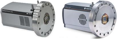
Examples of vacuum environments onto which Andor ‘open front’ ‘SO’ detectors can be attached are shown on fig. 1.
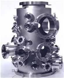
Vacuum Chamber
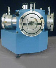
Vacuum Ultraviolet (VUV) spectrograph
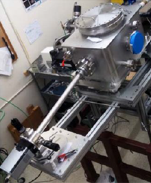
Extreme Ultraviolet (EUV/XUV) spectrograph
Figure 1 – Example of vacuum assemblies accepting Andor ‘SO’ detectors
Materials for use in vacuum should:
A bake-out process is used to force impurities out of the surfaces exposed to the vacuum, as these could cause outgas and impact on the quality of the vacuum. This could in turn affect the detector minimum cooling temperatures.
Andor vacuum flanges are machined from stainless steel 304 grade.
There are 3 main flange standards used to couple cameras to vacuum enclosures. These formats are described in the following sections:
Other flange standards, such as Japanese ‘JIS’[3] or Korean ‘KS’, can be considered through Andor's Customer Special Request (CSR) process. Please contact your local Andor representative for further information.
Andor detectors can be integrated on a number of 3rd party VUV, EUV or XUV spectrographs, including McPherson[4] or H+P Spectroscopy[5]. However these spectrographs may not be designed with the connection standards listed above.
Please refer to the McPherson spectrograph section of this document for further details on available options. For any other option, please contact your local Andor representative for further information.
This flange format is based on a metal-to-metal sealing by mean of a knife-edge interface. It is suitable for operation in environments ranging from atmospheric pressure to ultrahigh vacuum (< 10−13 Torr or < 1.3x10⁻¹³ mbar) - Researchgrade ‘direct detection’, open-front cameras are compatible with pressure environments down to 10-8 / 10-9 mbars.
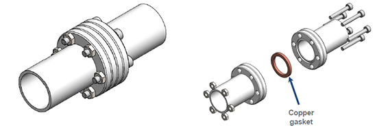
Figure 2 – Typical CF flange interface, with soft metal gasket shown on the drawing on the right
A knife-edge sealing involves a sharp-edged wedge of hard material on one side of the flange that cuts into a soft metal gasket on the mating part as the attachment bolts are tightened. The ductility of the soft metal (e.g. oxygen-free copper) gasket is used to fill small defects in the flange, providing an extremely leak-tight seal while also compensating for potential thermal expansion mismatch during bake-out up to ~ 450°C. Note that detectors cannot be exposed to such temperature – the maximum sustainable bake-out temperature for Andor cameras is +55°C.
Two different definition standards exist to specify this flange formats – equivalences are shown in table 3:
| Europe, Asia [ID, mm] | America [OD, inches] | Notes |
| DN10CF | 1 | (1) |
| DN16CF | 1⅓ ("mini") | (1) |
| DN25CF | 2⅛ | (1) |
| DN40CF | 2¾ | (1) |
| DN50CF | 3⅜ | (1) |
| DN50CF | 4½ | (2) |
| DN75CF | 4⅝ | (1) |
| DN100CF | 6 | (3) |
| DN125CF | 6¾ | (5) |
| DN160CF | 8 | (4) (5) |
| DN200CF | 10 | (5) (6) |
| DN250CF | 12 | (5) (6) |
Table 3 – Equivalence of common CF flange formats
(1) Not suitable for Andor cameras | (2) Suitable for Newton and iKon-M | (3) Andor standard CF configuration for Newton, iKon- M and iKon-L platforms | (4) Andor standard CF configuration for iKon-XL | (5) These I.D. can also be accommodated for Newton, iKon-M and iKon-L. Please contact your local Andor representative for further information | (6) These I.D. can also be accommodated for iKon-XL. Please contact your local Andor representative for further information.
The following table summarises Andor’s standard flange interface technical characteristics. Please contact your local Andor representative for alternative formats:
| Camera platform (a) | Newton DO920P-xx | iKon-M DO934P-xx | iKon-L DO936N-*0W-xx (c) | iKon-XL XLO-EAyy-C0 |
| Vacuum chamber standards compatibility | DN100CF / 6” CF / CF-152 | DN100CF / 6” CF / CF-152 | DN100CF / 6” CF / CF-152 | DN160CF / 8” CF / CF-203 |
| Outer diameter (OD) (b) | 5.96” [151.6 mm] | 5.96” [151.6 mm] | 5.96” [151.6 mm] | 7.97” [202.4 mm] |
| Inner diameter (ID) (b) | 1.97” [50.0 mm] | 1.97” [50.0 mm] | 2.68“ [68.0 mm] | 4.41” [112 mm] |
| Knife-edge diameter (KD) | 4.52” [114.9 mm] | 4.52” [114.9 mm] | 4.54“ [115.3 mm] | 6.525” [165.7 mm] |
| Mounting holes PCD | 16 x ø8.5 mm thru on PCD ø130.3 mm | 16 x ø8.5 mm thru on PCD ø130.3 mm | 16 x threaded on PCD ø130.3 mm | 20 x ø8.5 mm thru on PCD ø181.1 mm |
| Mounting holes format | Clearance for M8 or 5/16 UNC bolts | Clearance for M8 or 5/16 UNC bolts | Threaded holes (c) | Clearance for M8 or 5/16 UNC bolts |
| Bolt mounting direction | From camera to vacuum chamber | From camera to vacuum chamber | From vacuum chamber to camera | From camera to vacuum chamber |
| Flange orientation | Rotatable (11.25º increments) | Rotatable (11.25º increments) | Fixed (mounting hole at 12 o’clock) | Rotatable (11.25º increments) |
| Flange to sensor plane distance (nominal) | 0.13“ [3.2mm] | 0.13“ [3.2mm] | 0.24” [6.1mm] | 0.24” [6.1mm] |
| Filter holder type | Bayonet (d) | Bayonet (d) | Screw-in (e) | Screw-in (e) |
Table 4 – Andor standard CF interfaces definition
(a) xx = sensor code, e.g. BN, BR-DD; yy = sensor code identifier (iKon-XL only) | (b) The O.D. is used to describe the camera flange, while the I.D. is specified according to the sensor size | (c) There are 3 specific threaded hole options for iKon-L: a) M8 thread built into the flange - camera code *= M0W, b) 5/16 UNC thread built in to flange - camera code *= I0W, c) Encapsulated nut (either M8 or 5/16UNC) – camera code *= 00W [nuts can be removed and replaced if thread is worn] | d) Included with camera | (e) Optional
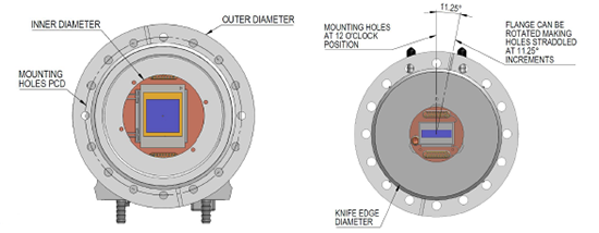
Figure 3 – Details of flange characteristic dimensions
This flange format is based on an O-ring seal. It is suitable for operation in environments ranging from atmospheric pressure to high vacuum (10−8 Torr or 1.3x10⁻⁸ mbar). - Research-grade ‘direct detection’, open-front cameras can work with pressure environments down to 10-6 / 10-7 mbars. The ISO format includes two main variations:
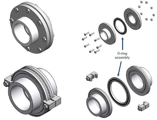
Figure 4 – ISO-F (top) and ISO-K (bottom) flange interface with assembled (left) and exploded view (right)
The O-ring assembly consists of a centring metal ring and an O-ring wrapped around it. The two flange mating parts are designed with a groove that is used to centre the O-ring assembly while tightening the attachment bolts or clamps.
This interface can sustain bake-out temperatures up to ~ 150oC. Note that detectors cannot be exposed to such temperature – the maximum sustainable bake-out temperature for Andor cameras is +55oC.
ISO flange formats are identified by the nominal internal diameter (I.D.) in millimetres, e.g. an ISO-K 100 or ISO-F 100 have an internal diameter of 100 mm. The standard sizes range from ISO-63 to ISO-630[6].
ISO-K 100 or ISO-F 100 are recommended for Newton and iKon-M series, but can also be provided for iKon-L. Other larger O.D. can however be accommodated. Please contact your local Andor representative for further information.
This flange format – also known as Klein Flange (or KF) - is also based on an O-ring seal. It is suitable for operation in environments ranging from atmospheric pressure to high vacuum (10−8 Torr or 1.3x10⁻⁸ mbar).
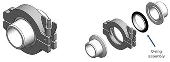
Figure 5 – KF flange interface with assembled (left) and exploded view (right)
The O-ring assembly consists of a centring metal ring and an O-ring wrapped around it. The two mating parts of the flange are designed with a chamfered lip and an interface to locate the O-ring assembly. A circular claw with a wingnut (or thumbscrew) is used to compress the O-ring assembly and the two flange parts to create the seal.
This interface can sustain bake-out temperatures up to ~ 150°C. Note that detectors cannot be exposed to such temperature – the maximum sustainable bake-out temperature for Andor cameras is +55°C.
KF flange format is identified by the nominal internal diameter (I.D.) in millimetres, e.g. an KF100 has an internal diameter of 100 mm. The standard sizes range from KF10 to KF50[6].
Please contact your local Andor representative for further information on options available.
Andor Newton CCD detectors options -995 can connect readily to the spectrographs listed in table 5.
The Newton -995 cameras (e.g. DO920P-BN-995 or DO940P-BN-995) coupling interface is an O-ring sealed flange, designed with the sensor image plane sitting 5.4 mm behind the faceplate front and with a 38 x 25mm aperture. Please refer to[7] for software control of these spectrographs, and see appendix A for further details on the cameras.
| Model number | Wavelength Range (nm) | Focal length (mm) | Spectral resolution (nm) | Multi-track | High vacuum | Optical design | |
| 234/302 | VUV | 30 to 550 | 200 | 0.1 | - | Yes | Concave Holographic |
| 225 | VUV | 30 to 1,200 | 1,000 | 0.015 | Yes | Yes | Normal Incidence |
| 248/310G | Soft X-ray EUV, XUV | < 1 to 310 | 1,000 | 0.018 | - | Yes | Grazing Incidence |
Table 5 – Main VUV/EUV/XUV spectrographs compatible with Andor -995 flange variation
Andor open-front ‘SO’ cameras can be coupled to filters to remove the unwanted contribution of low energy radiations on the useful signal.
For x-ray experiments with useful information in the energy range 3-30 keV (‘direct’ x-ray detection with a siliconbased detector), thin foils of Beryllium (Be) or Aluminium (Al) are typically used. Typical transmission characteristics of Beryllium filters as a function of thickness are shown on fig. 6.
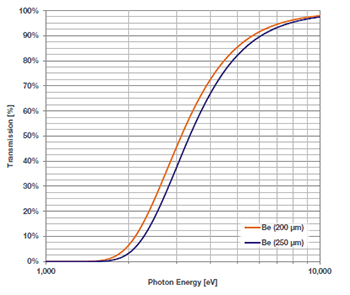
Figure 6 – Typical Beryllium filters transmission curves versus material thickness
| Camera platform | Standard Be filter thickness | Standard Be filter diameter [clear aperture] | Min. recommended thickness * |
| Newton SO | 250 μm | Ø45.5 ±0.2 mm [Ø35.0mm] | 200 μm |
| iKon-M SO | 250 μm | Ø45.5 ±0.2 mm [Ø35.0mm] | 200 μm |
| iKon-L SO | 250 μm | Ø60.0 ±0.2 mm [Ø45.0mm] | 250 μm |
| iKon-XL SO | 250 μm | Ø105.0 ±0.2 mm [Ø95.0mm] | 250 μm |
Table 6 – Standard filter thickness for Andor open-front ‘SO’ platforms
* available through CSR – thinner windows carry increased risks of breakage, long-term stress
Other filter options[8] may be considered through Andor’s CSR process. Please contact your local Andor representative for further information. See Appendix B for further information on filters and filter holders.
There are two options for coupling filters to Andor open-front ‘SO’ cameras:
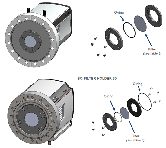
Figure 7 – Newton and iKon-M (top) and iKon-L (bottom) vacuum chamber-compatible filter holders
The filter holders SO-FILTER-HOLDER-xx have a built-in pumping channel to ensure pressure equilibrium on either side of the filter, hence minimizing the risk of mechanical stress and damage to the filter.
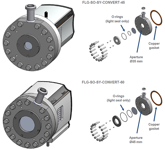
Figure 8 – SO-to-SY filter holder assembly for Newton & iKon-M (top) and iKon-L (bottom) open-front ‘SO’ platforms
FLG-SO-SY-CONVERT-45 mounts onto the Newton and iKon-M ‘SO’ camera series. FLG-SO-SY-CONVERT-60 mounts onto the iKon-L ‘SO’ camera series. The vacuum sealing interface is a knife-edge.
The vacuum between the filter and the sensor is achieved by connecting a pump to the interface highlighted on fig. 7, which is fitted with a KF16 interface. Note that since this interface relies on an O-ring vacuum seal, pressure down to 10-6 mbar can be achieved. Continuous pumping is recommended to maintain the highest degree of vacuum, and also ensure access to the lowest camera cooling temperature.
Newton CCD platform and iKon-M CCD platform
Newton CCD platform and iKon-M CCD platform
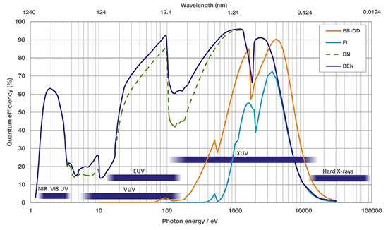
Sensor type key:
BN: Back-illuminated un-coated sensor
BR-DD: Back-illuminated AR coated deep-depletion sensor
FI: front-illuminated
Note that other sensors could be considered for integration into Andor ‘open-front’ ‘SO’ platforms – please contact your local Andor representative for further details
BN-DD: Back-illuminated deep-depletion un-coated sensor – increased higher energy QE versus -BN type
FI-DD: Front-illuminated deep-depletion sensor – increased higher energy QE versus -FI type
| Newton DO920P-XX | Newton DO920P-BN-995 | Newton DO940P-XX | Newton DO940P-BN-995 | |
| Sensor format | 1024 x 255 matrix 26 μm pixels e2v CCD 30-11 |
2048 x 512 matrix 13.5 μm pixels e2v CCD 42-10 |
||
| Sensor Size | 26.7 x 6.7 mm | 27.6 x 6.9 mm | ||
| Sensor options (-XX) | BEN, BR-DD, FI | BEN | BEN, BN, FI | BEN, BN |
| Minimum TE-cooling temperature | -100 °C | -100 °C | -100 °C | -100 °C |
| Maximum spectral rate | 273 sps (>1,580 with crop mode) | 122 sps (>940 with crop mode) | ||
| Pixel well depth | 500,000 e- | 100,000 e- | ||
| Register well depth | 1,000,000 e- | 150,000 e- (HS mode) 600,000 e- (HC mode) |
||
| Readout noise | 4 e- @ 50 kHz readout | 3.5 e- @ 50 kHz readout | ||
| PC interface | USB 2.0 | |||
| Flange interface | DN100CF / 6” CF / CF-152 | O-ring seal, sensor 5.4 mm behind faceplate, 38 x 25 mm aperture | DN100CF / 6” CF / CF-152 | O-ring seal, sensor 5.4 mm behind faceplate, 38 x 25 mm aperture |
| Detectors for imaging | iKon-M DO934P-XX | iKon-L DO936N-*0W-XX | iKon-XL 230 XLO-EAxx-C0 | iKon-XL 231 XLO-EAxx-C0 |
| Sensor format | 1024 x 1024 matrix 13 μm pixels e2v CCD 47-10 |
2048 x 2048 matrix 13.5 μm pixels e2v CCD 42-40 |
e2v CCD 230-84 4096 (H) x 4112 (V) matrix 15 μm pixels |
e2v CCD 231-84 4096 (H) x 4112 (V) matrix 15 μm pixels |
| Sensor Size | 13.3 x 13.3 mm | 27.6 x 27.6 mm | 61.4 x 61.7 mm | |
| Sensor options (-XX) | BEN, BN, BR-DD, FI | BEN, BN, BR-DD, FI | BN | BEN, BN, BR-DD |
| Minimum TE-cooling temperature | -100 °C | -100 °C | -75 °C | |
| Maximum image rate | 4.4 fps | 0.95 fps | >0.5 fps | >0.35 fps |
| Pixel well depth | 100,000 e- | 100,000 e- 150,000 e- [BR-DD] |
150,000 e- | 350,000 e- |
| Output node capacity well depth | 250,000 e- | 1,000,000 e- | 450,000 e- [HS] 900,000 e- [HC] |
600,000 e- |
| Readout noise | 2.9 e- @ 50 kHz 3.3 e- @ 50 kHz [BR-DD] |
2.9 e- @ 50 kHz 4.3 e- @ 50 kHz |
4.5 e- @ 100 kHz | 2.1 e- @ 100 kHz |
| PC interface | USB 2.0 | USB3.0, fibre-optic | ||
| Flange interface | DN100CF / 6” CF / CF-152 | DN100CF / 6” CF / CF-152 | DN160CF / 8” CF / CF-203 | |
Table 7 – Andor ‘Open-front’ cameras key specifications
| Camera platform | Filter holder part number | Standard Be filter dimensions (Ø x thickness) | Standard filter part number (order seperatly) | Min. recommended thickness * | Max. recommended thickness |
| Newton | Included with camera | Ø45.5 mm x 250 μm | ACC-OPT-02839 | 200 μm | 500 μm |
| iKon-M | Included with camera | Ø45.5 mm x 250 μm | ACC-OPT-02839 | 200 μm | 500 μm |
| iKon-L | SO-FILTER-MNT-IKONL | Ø60.0 mm x 250 μm | ACC-OPT-03838 | 250 μm | 500 μm |
| iKon-XL | SO-FILTER-MNT-IKONXL | Ø105.0 mm x 250 μm | ACC-OPT-10395 | 250 μm | 500 μm |
Table 8 – Standard filter and holder references for Andor open-front ‘SO’ platforms
* available through CSR – thinner windows carry increased risks of breakage, long-term stress
Note: Copper gasket for CF ConflatTM flanges can be sourced from a number of vendors. This part can also be ordered from Andor under the reference ACC-FLG-SO-GSKT-CU.
Q1: Does the vacuum chamber pressure impact the minimum cooling temperature achievable by an ‘openfront’ ‘SO’ camera?
A1: No impact on cooling temperatures for pressure below ~10-5 mbar
Q2: What information should be provided for custom ConflatTM flange design?[6]
| Parameter | Value | Notes |
| Vacuum chamber standards compatibility? | e.g. DN200CF or 12” (if applicable) | |
| Outer diameter? | mm or inches | Ø45.5 mm x 250 μm |
| Inner diameter? | mm or inches | this can refer to the clear aperture around the sensor |
| Knife-edge diameter? | mm or inches | |
| Mounting holes pitch circle diameter (PCD)? | mm or inches | |
| Mounting hole format? | mm or inches | e.g. M8 or 3⁄8 |
| Bolts mounting direction? | this is the direction from which the screws should inserted from, e.g. camera flange-to-vacuum chamber, or vacuum chamber-to-camera flange | |
| Flange rotation? | e.g. Yes/No, step granularity (in degrees) | |
| Flange to sensor plane distance (nominal) | mm or inches | from the front face of the camera to the sensor plane |
| Filter holder requirement | e.g. Yes / No, filter type / material / thickness |
Q3: Can Andor ‘SO’ cameras accommodate existing vacuum chamber setups designed with ‘straddled’ flange configuration?
| Platform | 6” flange ‘straddled’ configuration | 4.5” flange ‘straddled’ configuration |
| Newton ‘SO’ | ? YES Newton ‘SO’ models can accommodate 11.25º step rotation as standard Flange to sensor plane distance = 0.13“ [3.2mm] Compatible with standard Newton ‘SO’ bayonet filter holder configuration [included] |
! More information required Please contact your local Andor representative do discuss your specific VUV/EUV/XUV spectrograph focal plane configuration |
| iKon-M ‘SO’ | ? YES iKon-M ‘SO’ models can accommodate 11.25º step rotation as standard Flange to sensor plane distance = 0.13“ [3.2mm] Include standard iKon-M ‘SO’ bayonet filter holder |
? YES Variation ‘-9NP’ (e.g. DO934P-BN-9NP) can accommodate straddled configuration Flange to sensor plane distance = 0.23“ [5.9 mm] Include bayonet filter holder |
| iKon-L ‘SO’ | ? YES Variation ‘-9OW’ (e.g. DO936N-*0W-BN-9OW) can accommodate straddled configuration Flange to sensor plane distance = 0.24“ [6.1 mm] Include standard iKon-L ‘SO’ screw-in filter holder |
Not available |
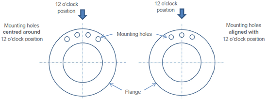
Figure 10 – Illustration of vacuum flanges with ‘straddled’ configuration (left) and Andor standard configuration (right)
Q4: What information should be provided for ISO flange design?[6]
| Parameter | Value | Notes |
| Vacuum chamber standard compatibility (if any)? | e.g. ISO-F 100 or ISO-K 100 | |
| Tube outer diameter? | mm or inches | |
| Flange outer diameter? | mm or inches | |
| Flange thickness? | mm or inches | |
| Number of bolts (ISO-F)? | e.g. 8x Ø9 mm on Ø145 mm | |
| Centring O-ring assembly characteristics? | e.g. ISO 100 format, or alternatively define the lip internal and external diameter (mm or inches) and the thickness (mm or inches) | |
| Bolts mounting direction? | this is the direction from which the screws should inserted from, e.g. camera flange-to-vacuum chamber, or vacuum chamber-to-camera flange | |
| Flange rotation? | e.g. Yes/No, step granularity (in degrees) | |
| Flange to sensor plane distance (nominal) | mm or inches | from the front face of the camera to the sensor plane |

© Oxford Instruments 2026
