System Overview
Power Connections
Power connections for the Versatile Laser Engine and the BCU are identified in the diagrams provided in Rear Panel and Rear panel of the BCU.
As shown below, the BCU is connected via the PS-1
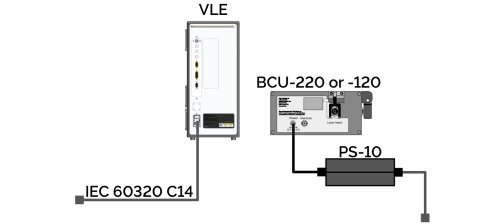
Power connections for Versatile Laser Engine and BCU configuration diagram.
Please see Electrical Power Specifications and Power Supply Information for further information.
Optical Connections
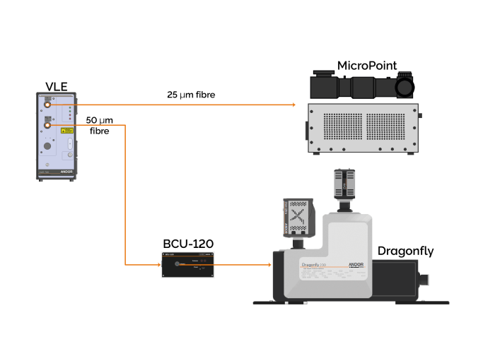
Overview of standard single VLE as part of an overall system, with two output couplers
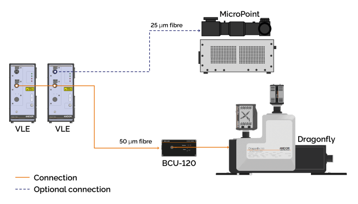
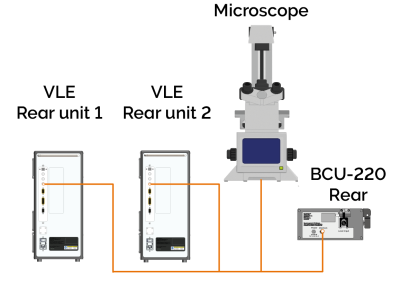
Overview of standard dual VLE as part of an overall system, with two output couplers.
Interlock Connections
A BNC connector is provided so that the user can interlock the Versatile Laser Engine lasers. The contacts must be shorted for the lasers to operate. When the interlock contacts are open, the primary shutter closes, and all the lasers are disabled.
When the interlock contacts are open, the primary shutter closes, and all the lasers are disabled.
-
When the microscope interlock is opened, the user must close the interlock and the laser configuration will be re-established.
Interlock connection schematic for single Versatile Laser Engine.
Interlock connection schematic for dual Versatile Laser Engine.
Laser Blanking Connections
These connections will be set up by your installation engineer. If you require further assistance please contact Andor customer support.