Rear Panel
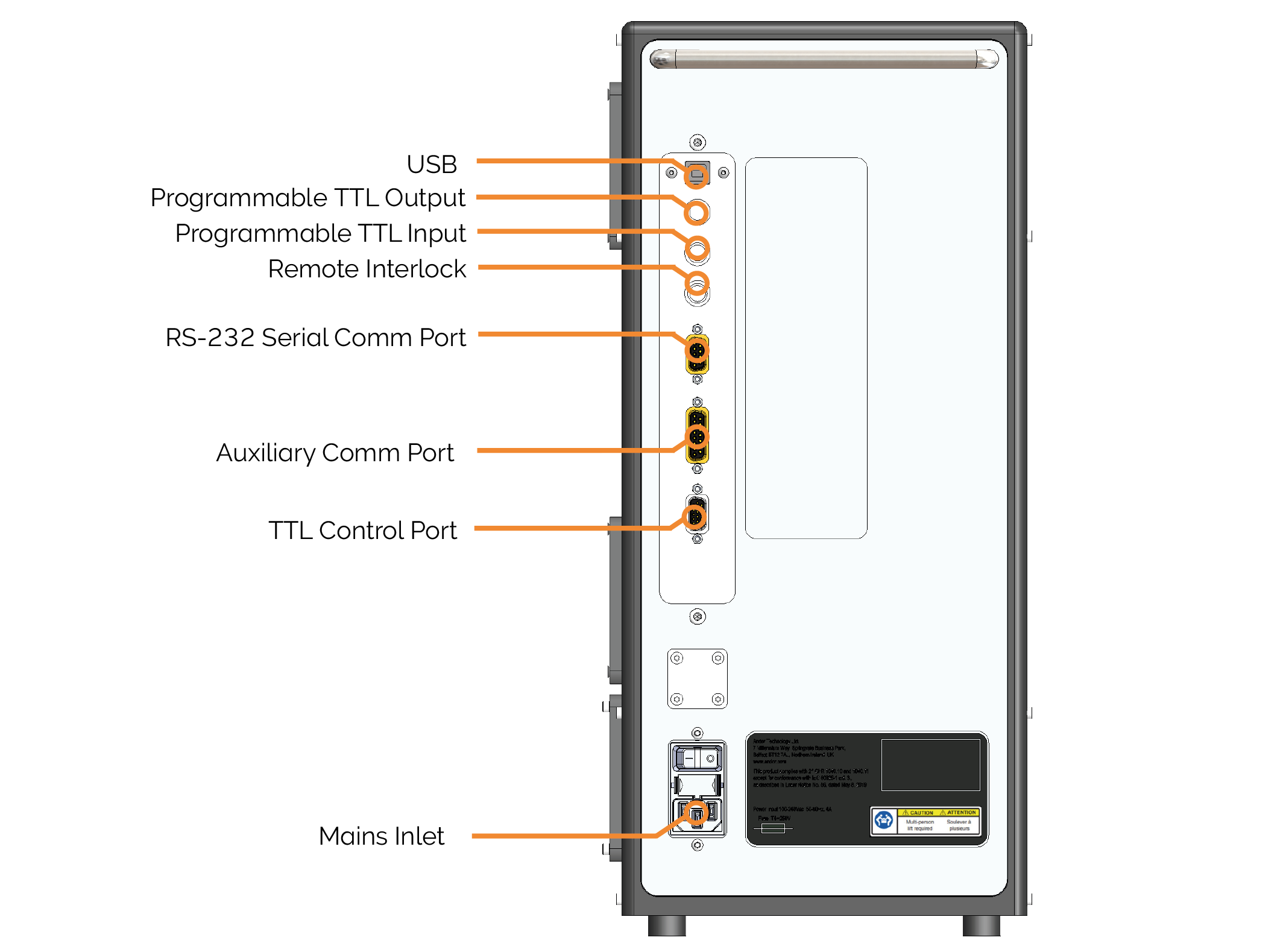
Versatile Laser Engine rear panel.
Rear panel connector types.
| Connection | Description |
|---|---|
| USB | USB 2.0 Standard Series B Receptacle |
| Programmable TTL Output | BNC socket |
| Programmable TTL Input | BNC socket |
| Remote Interlock | BNC socket |
| RS-232 Serial Comm Port | Standard 9-pin D-sub (DE-9) female socket |
| Auxiliary Comm Port | Reserved (not available to the user) |
| TTL Control Port | High-density 15-pin D-sub (DE-15) female socket |
| 12 V DC Input | 2 POS circular connector plug, female |
| Mains Inlet | Mains inlet connector type (IEC 60320-1 C14) |
USB/RS-232
Either of the USB or the RS-232 connections may be used to communicate with the Versatile Laser Engine to control and monitor the lasers and other functions. The RS-232 uses the following settings: 19200 bps, 8 data bits, 1 stop bit, no parity, no hardware flow control. The USB connection uses the human interface device (HID) protocol and is automatically detected by compatible software programs. The USB can be connected to any USB port on the PC.
Programmable TTL Input/Output
Two BNC connectors are provided on the rear panel to allow the user to synchronize external equipment with the Versatile Laser Engine. Any common type of coaxial cable may be connected to the BNC connector including 50 Ω and 75 Ω types. Wire leads may also be used with an appropriate BNC coaxial to wire adapter. The Programmable TTL Input is by default configured to provide synchronization to an external camera fire signal. A high TTL level turns on any selected lasers and a low-level blanks the Versatile Laser Engine output. Synchronization is initiated by turning on the desired laser through the Versatile Laser Engine software interface, and then the selected lines will automatically be blanked when the TTL signal goes low and restored when the signal goes high. The TTL input is capable of driving lasers with less than one microsecond response time although the exact response time may be limited by the laser (see TTL Input/Output Specifications).
Remote Interlock
A BNC connector is provided so that the user can interlock the Versatile Laser Engine lasers using external switches or sensors present on microscopes, doors, etc. The contacts must be shorted for the lasers to operate. Please see Interlock Connections for more information.
TTL Control Port
The HD15 D-sub connector provides the user with the capability of controlling the lasers via TTL control. The pinouts for this connector are provided below.
TTL pin out information
| Pin | Function |
|---|---|
| 1 | +5 V Output 1 |
| 2 | Dual output switch 2 |
| 3 | Ground |
| 4 | TTL in 5 2 |
| 5 | TTL in 6 2 |
| 6 | TTL in 7 2 |
| 7 | Control Input 2 (for triple output system) |
| 8 | TTL in 1 2 |
| 9 | TTL in 2 2 |
| 10 | TTL in 3 2 |
| 11 | TTL in 4 2 |
| 12 | Reserved |
| 13 | Reserved |
| 14 | Reserved |
| 15 | Reserved |
|
|
Mains Inlet
A power switch is located above the power input socket (IEC 60320 C14 mains inlet) on the rear panel of the Versatile Laser Engine.