System Overview
Power Connections
Power connections for the High Power Laser Engine and the BCU are identified in the diagrams provided in Rear Panel and Rear panel of the BCU.
As shown below, the BCU is connected via the PS-1
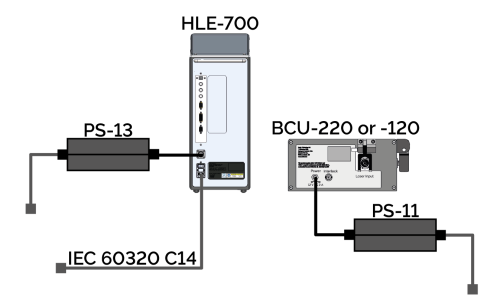
Power connections for High Power Laser Engine and BCU configuration diagram.
Please see Electrical Power Specifications
Optical Connections
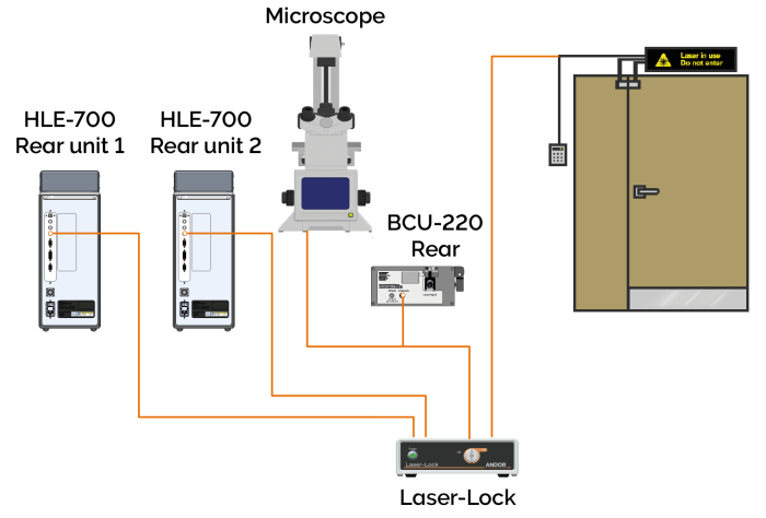
System overviews are provided below for both a single and dual HLE-700 system set up. A system overview is provided below for a typical triple output HLE connected to a Mosaic, Micropoint and Dragonfly (via the BCU) in Figure 15. A typical system overview for a dual HLE-700 is provided in Figure 16. For models with multiple output couplers Mosaic is always connected to the top output coupler. If the HLE contains a single output coupler this connects to the BCU.
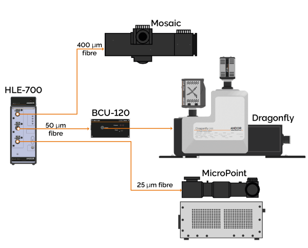
Overview of standard single HLE-700 as part of an overall system, with three output couplers
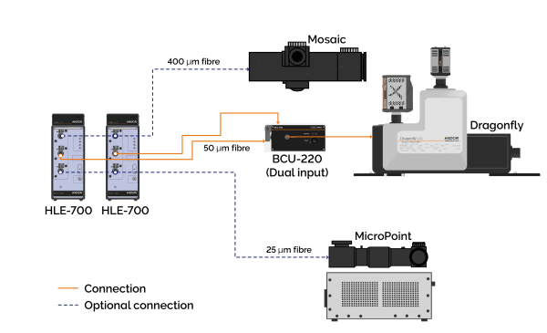
Overview of standard dual HLE-700 as part of an overall system, with three output couplers.
Interlock Connections
A BNC connector is provided so that the user can interlock the High Power Laser Engine lasers
The output of the Laser-Lock is connected to a BNC interlock input on the back of the High Power Laser Engine. The contacts on both inputs must be shorted for the lasers to operate.
When the interlock contacts are open, the primary shutter closes, and all the lasers are disabled.
-
When the microscope interlock is opened, the user must close the interlock and the laser configuration will be re-established.
-
When the remote interlock is opened the user must close the interlock and then push the button on the Laser-Lock.
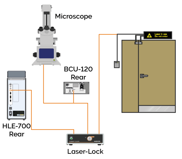
Interlock connection schematic for single High Power Laser Engine.
Interlock connection schematic for dual High Power Laser Engine.
The Laser-Lock port connections for the single and dual High Power Laser Engine system set up are provided in the table below.
Laser-Lock rear panel connections for single and dual High Power Laser Engineconfigurations.
| Port | Single |
Dual |
|---|---|---|
| Laser device 1 |
|
|
| Laser device 2 | - |
|
| Laser device 3 | - | |
| Laser device 4 | - | |
| Microscope interlock sensor | Microscope and BCU | |
| Remote interlock sensor | Remote interlocks, e.g. door | |
Please see the separate user guide for the Laser-Lock box available at andor.oxinst.com/downloads for further information on its functionality.
Laser Blanking Connections
These connections will be set up by your installation engineer. If you require further assistance please contact Andor customer support.