Rear Panel
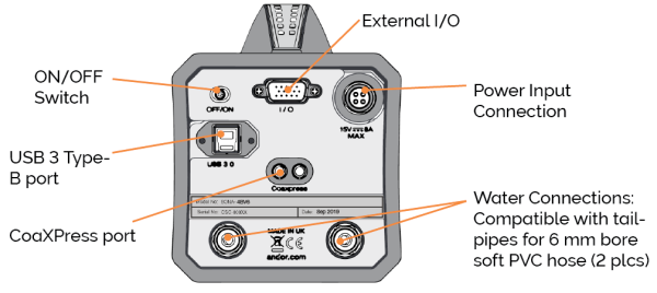
USB Connectivity
USB 3 connection provides a robust high speed connection to the control PC.
CoaXPress Connectivity
CoaXPress connectivity, available on upgraded models only, provides a robust, high speed, 2-lane connection to the control PC.
External I/O: TTL / Logic
The TTL/Logic connection permits connection to other devices for synchronisation and control of fire, trigger and shutter operations. Connector type: D-type to BNC cable Fire (Output), External Trigger (Input), ARM.
Liquid Cooling Connections
Liquid cooling connections provide the facility for connection to a liquid cooling system. Refer to Connecting a Cooling System.
Power Connector
Power input connection (15 V DC) for connection to the PSU. Refer to Power Supply Information. An ON/OFF switch is also present.
Multi I/O Timing Cable Pin Outs
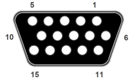
Pinouts for the 15-way D type connector
| Available using standard 3-way cable | Available using optional 7-way cable | ||||||
|---|---|---|---|---|---|---|---|
| Pin | 3-way cable | Pin | 3-way cable | Pin | 7-way cable | Pin | 7-way cable |
| 1 | ARM | 9 | Reserved | 1 | ARM | 9 | Reserved |
| 2 | AUX_OUT_1 | 10 | Reserved | 2 | AUX_OUT_1 | 10 | Reserved |
| 3 | Reserved | 11 | Reserved | 3 | FIRE n | 11 | Reserved |
| 4 | Reserved | 12 | Reserved | 4 | FIRE | 12 | Reserved |
| 5 | Reserved | 13 | Reserved | 5 | AUX_OUT_2 | 13 | Reserved |
| 6 | Ground | 14 | Reserved | 6 | Ground | 14 | Reserved |
| 7 | External Trigger | 15 | Reserved | 7 | External Trigger | 15 | Reserved |
| 8 | Reserved | 8 | Spare | ||||
-
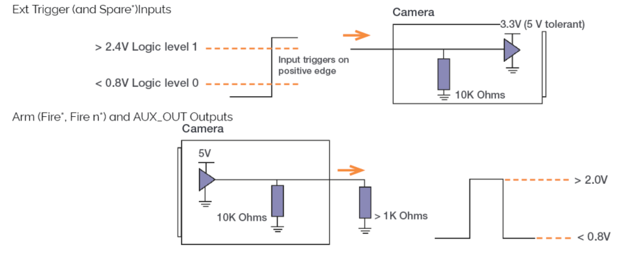
External Trigger (and Spare inputs) are 5 V TTL input. By default they trigger on a rising edge.
-
ARM and AUX_OUT_1 (FIRE, FIRE n and AUX_OUT_2: for 7-way cable only) outputs are all TTL timing outputs. These can be individually inverted via software (e.g. Solis or SDK).
-
AUX_OUT_1 supplies the ‘FIRE ALL’ output by default. This is the logical AND of the FIRE pulses associated with Row #1 and Row #n (the last row read out in the image frame). Therefore the FIRE ALL pulse represents the time within a frame when all rows on the sensor are simultaneously exposing.
-
AUX_OUT_1 is configurable for TTL timing outputs FIRE, FIRE n and FIRE ANY. The FIRE ANY pulse represents the time within a frame when any row of the image frame is exposing. Refer to Trigger Modes for the behaviour of these signals and to the SDK3 manual for configuring the AUX_OUT_1 output.
-
AUX_OUT_2 output defaults to shutter control.
-
Optional 7-way multi I/O timing interface cable (Andor part number ACC-ACZ-05612) gives access to all of the above I/O functions shown in the table above right (excluding Ground and Reserved pins).
-
Reserved pins should not be used.
* using optional 7-way multi I/O timing cable only
Impedance Information
Sona and Marana-11 sCMOS connection impedance information