Product Overview
This section provides an overview of Versatile Laser Engine models.
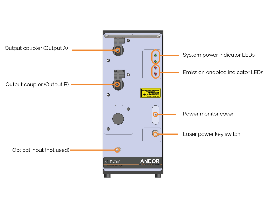
Versatile Laser Engine front panel.
Output Couplers
Laser is emitted from the unit via the output couplers. A single output is standard but dual output
| Warning |
|---|
| Never remove the fibre lock when in operation. The cable should only be disconnected by qualified service personnel. A tool is required to open the locking mechanism once closed. |
Laser Power Key Switch
The Laser Power Key Switch on the front panel of the Versatile Laser Engine disconnects electrical power to all the lasers via a control circuit if it is in the OFF position.
The key cannot be removed when the switch is in the ON position, but it can be removed when the switch is in the OFF position.
System Power and Emission Enabled Indicator LEDs
The upper green system power indicator LEDs light when the rear panel mains rocker switch is turned ON. The internal AC/DC power supply is receiving power from the mains power supply.
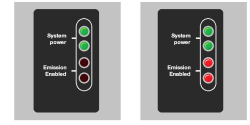
System power indicator LEDs and emission enabled indicator LEDs
The upper red LED is turned ON a few moments after the Laser Power Key Switch is turned on. The lower red LED is turned ON when the primary shutter is opened a few seconds after the laser power is turned on. This indicates that laser emission is possible and could be imminent. Both red LEDs are turned off if the interlock is open (See “Remote Interlock). Note that there are two LEDs for redundancy, in case one fails. If one LED fails, notify Andor Service.
Power Monitor Cover
The power monitor is only accessible to service personnel and not accessible to users.
Optical Input (Blanked)
Not used on Versatile Laser Engine.