Dual Amplifier Dynamic Range
The Dual Amplifier architecture of the sCMOS sensor in Zyla eliminates the need to choose between low noise or high capacity, in that signal can be sampled simultaneously by both high gain and low gain amplifiers. As such, the lowest noise of the sensor can be harnessed alongside the maximum well depth, affording the widest possible dynamic range. Traditionally, scientific sensors including CCD, EMCCD, ICCD and CMOS, demand that the user must select ‘upfront’ between high or low amplifier gain (i.e. sensitivity) settings, depending on whether they want to optimise for low noise or maximum well depth. Since the true dynamic range of a sensor is determined by the ratio of well depth divided by the noise floor detection limit, then choosing either high or low gain settings will restrict dynamic range by limiting the effective well depth or noise floor, respectively.
For example, consider a large pixel CCD, with 16-bit Analog to Digital Converter (ADC), offering a full well depth of 150,000 e- and lowest read noise floor of 3 e-. The gain sensitivity required to give lowest noise is 1 e-/ADU (or ‘count’) and the gain sensitivity required to harness the full well depth is 2.3 e-/ADU, but with a higher read noise of 5 e-. Therefore, it does not automatically follow that the available dynamic range of this sensor is given by 150,000/3 = 50,000:1. This is because the high sensitivity gain of 1 e-/ADU that is used to reach 3 e- noise means that the 16-bit ADC will top out at 65,536 e-, well short of the 150,000 e- available from the pixel. Therefore, the actual dynamic range available in ‘low noise mode’ is 65,536/3 = 21,843:1. Conversely, the lower sensitivity gain setting means that the ADC will top out at ~ 150,000 e-, but the higher read noise of 5 e- will still limit the dynamic range to 150,000/5 = 30,000:1 in this ‘high well depth mode’. The sCMOS sensor offers a unique dual amplifier architecture, meaning that signal from each pixel can be sampled simultaneously by both high and low gain amplifiers. The sensor also features a split readout scheme in which the top and bottom halves of the sensor are read out independently. Each column within each half of the sensor is equipped with dual column level amplifiers and dual analog-to-digital converters, represented by the block diagram below:
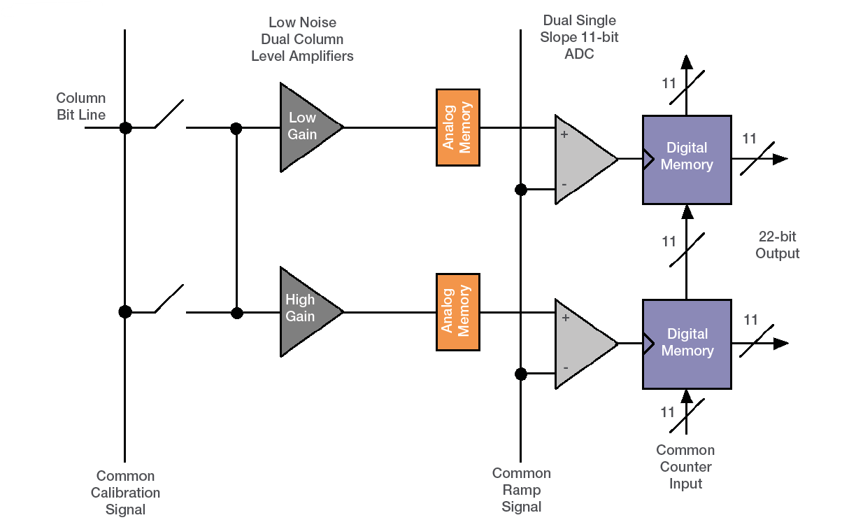
Amplifiers and ADC of the sCMOS Sensor
The dual column level amplifier/ADC pairs have independent gain settings, and the final image (High contrast image of fixed labeled cell. Intensity line profile through single row demonstrates pixel regions that were sampled by high gain (low noise) and low gain (high capacity) amplifiers.) is reconstructed by combining pixel readings from both the high gain and low gain readout channels to achieve a wide intra-scene dynamic range, uniquely so considering the relatively small 6.5 μm pixel pitch.
The method of combining signals from two 11-bit ADCs can be divided into four basic steps.
-
At the end of the analog chain the “Signal” voltage is applied to two independent amplifiers: the high gain amplifier and the low gain amplifier. This results in two separate digital data streams from the sensor
-
The camera selects which data stream to use on a pixel per pixel, frame by frame basis using a threshold method
-
The data is then compensated for DC offset and gain. Again, this is done on a pixel by pixel basis using the compensation data associated with the data stream. The gain corrects for pixel to pixel relative sensitivity, pixel node amplifier and the high and low amplifier relative gains
-
The pixels are then combined into a single 16-bit image for transfer to the PC
The user maintains the choice of opting to stay with 12-bit single gain channel data if dynamic range is not critical, resulting in smaller file sizes.
Typical performance of supported gain settings of the Zyla 5.5 (Jan 2012 onwards)
| Amplifier Gain (Current Andor SDK / Solis description) | Mode | Sensitivity e-/ ADU (typical) | Data Range | Effective pixel saturation limit / e- | Spooling File Size (per frame) |
|---|---|---|---|---|---|
| 12-bit (high well capacity) | GS/RS | 7.5 | 12-bit | 30,000 | 8 Mb |
| 12-bit (low noise) | GS | 0.42 | 12-bit | 1,700 | 8 Mb |
| 12-bit (low noise) | RS | 0.28 | 12-bit | 1,100 | 8 Mb |
| 16-bit (low noise and high well capacity) | GS | 0.45 | 16-bit | 30,000 | 10.5 Mb |
| 16-bit (low noise and high well capacity) | RS | 0.45 | 16-bit | 30,000 | 10.5 Mb |
Typical performance of supported gain settings of the Zyla 4.2
| Amplifier Gain (Current Andor SDK / Solis description) | Mode | Sensitivity e-/ ADU (typical) | Data Range | Effective pixel saturation limit / e- | Spooling File Size (per frame) |
|---|---|---|---|---|---|
| 12-bit (high well capacity) | RS | 7.5 | 12-bit | 30,000 | 6.1 Mb |
| 12-bit (low noise) | RS | 0.28 | 12-bit | 1,100 | 6.1 Mb |
| 16-bit (low noise and high well capacity) | RS | 0.45 | 16-bit | 30,000 | 8.1 Mb |
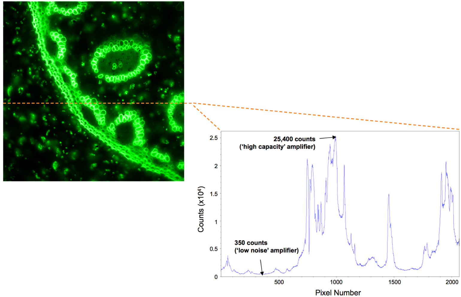
High contrast image of fixed labeled cell. Intensity line profile through single row demonstrates pixel regions that were sampled by high gain (low noise) and low gain (high capacity) amplifiers.