Understanding Read Noise in sCMOS
sCMOS technology boasts an ultra-low read noise floor that significantly exceeds that of even the best CCDs, and at several orders of magnitude faster pixel readout speeds. For those more accustomed to dealing with CCDs, it is useful to gain an understanding of the nature of read noise distribution in CMOS imaging sensors.
CCD architecture is such that the charge from each pixel is transferred through a common readout structure, at least in single output port CCDs, where charge is converted to voltage and amplified prior to digitization in the Analog to Digital Converter (ADC) of the camera. This results in each pixel being subject to the same readout noise. However, CMOS technology differs in that each individual pixel possesses its own readout structure for converting charge to voltage. In the sCMOS sensor, each column possesses dual amplifiers and ADCs at both top and bottom (facilitating the split sensor readout). During readout, voltage information from each pixel is fed directly to the appropriate amplifier/ADC, a row of pixels at a time
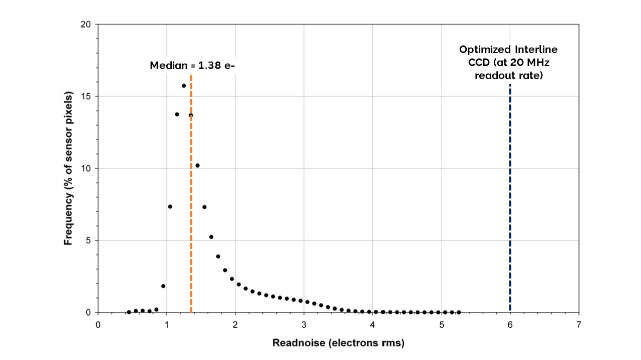
As a consequence of each pixel having its own individual readout structure, the overall readout noise in CMOS sensors is described as a distribution, as exemplified in Representative histogram showing read noise distribution at fastest readout speed of ZL41 Cell 5.5, 560 MHz (280 MHz x2). The median value of 1.38 e- means 50% pixels have read noise less than 1.38 e- and 50% have greater than 1.38 e-. The line at 6 e- represents a typical read noise value from a well optimized Interline CCD – all pixels in a CCD essentially share the same noise value below, which is a representative noise histogram from a ZL41 Cell 5.5 camera at the fastest readout speed of 560 MHz (or 280 MHz x 2 halves). It is standard to describe noise in CMOS technology by citing the median value of the distribution. In the data presented, the median value is 1.38 electron RMS. This means that 50% of pixels have a noise less than 1.38 electrons, and 50% have noise greater than 1.38 electrons. While there will be a small percentage of pixels with noise greater than 2 or 3 electrons, observable as the low level tail towards the higher noise side of the histogram, it must be remembered that a CCD Interline camera reading out at 20 MHz would have 100% of its pixels reading out with read noise typically ranging between 6 and 10 electrons RMS (depending on camera design).

Representative histogram showing read noise distribution at fastest readout speed of ZL41 Cell 5.5, 560 MHz (280 MHz x2). The median value of 1.38 e- means 50% pixels have read noise less than 1.38 e- and 50% have greater than 1.38 e-. The line at 6 e- represents a typical read noise value from a well optimized Interline CCD – all pixels in a CCD essentially share the same noise value